
Κατευθυντικές υδραυλικές βαλβίδες σειράς WEH με πιλοτική λειτουργία
Κατευθυντικές υδραυλικές βαλβίδες σειράς WEH με πιλοτική λειτουργία
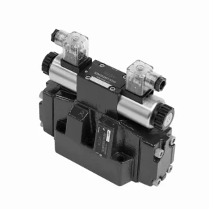
Οι κατευθυντικές υδραυλικές βαλβίδες της σειράς WEH με πιλοτική λειτουργία είναι προηγμένα εξαρτήματα που παρέχουν ακριβή και αποτελεσματικό έλεγχο των υδραυλικών συστημάτων. Σχεδιασμένες για να καλύπτουν τις απαιτήσεις διαφόρων βιομηχανιών, αυτές οι βαλβίδες προσφέρουν εξαιρετική απόδοση, αξιοπιστία και ευελιξία.
Οι κατευθυντικές υδραυλικές βαλβίδες της σειράς WEH με πιλότο είναι αξιόπιστα, υψηλής απόδοσης εξαρτήματα που δίνουν στους χειριστές τη δυνατότητα ακριβούς ελέγχου και αποτελεσματικής διαχείρισης ρευστών σε υδραυλικά συστήματα. Με τον σχεδιασμό τους με πιλότο, τον εξαιρετικό κατευθυντικό έλεγχο, ένα ευρύ φάσμα διαμορφώσεων και την υψηλή χωρητικότητα ροής, αυτές οι βαλβίδες προσφέρουν την αξιοπιστία και την ευελιξία που απαιτούνται σε διάφορους κλάδους. Ακολουθώντας τις συνιστώμενες μεθόδους χρήσης και τηρώντας τις τακτικές πρακτικές συντήρησης, οι βαλβίδες της σειράς WEH θα συνεχίσουν να παρέχουν εξαιρετική απόδοση. Αναβαθμίστε το υδραυλικό σας σύστημα με τις κατευθυντικές υδραυλικές βαλβίδες της σειράς WEH και ζήστε τα οφέλη της ακρίβειας, του ελέγχου και της αξιοπιστίας.
Κατευθυντικές υδραυλικές βαλβίδες σειράς WEH με πιλοτική λειτουργία Βασικά χαρακτηριστικά:
- Σχεδιασμός με πιλοτική λειτουργία:
- Οι βαλβίδες της σειράς WEH χρησιμοποιούν σχεδιασμό με πιλότο, ο οποίος βελτιώνει την απόκριση και την ακρίβεια ελέγχου τους.
- Αυτός ο σχεδιασμός επιτρέπει στις βαλβίδες να χειρίζονται εφαρμογές υψηλής πίεσης, εξασφαλίζοντας εύκολα βέλτιστη απόδοση.
- Κατευθυντικός έλεγχος:
- Αυτές οι υδραυλικές βαλβίδες υπερέχουν στην παροχή ακριβούς κατευθυντικού ελέγχου του υδραυλικού υγρού.
- Οι χειριστές μπορούν εύκολα να διαχειριστούν τη ροή του ρευστού και να την κατευθύνουν σε διαφορετικούς ενεργοποιητές ή εξαρτήματα εντός του υδραυλικού συστήματος.
- Ευρύ φάσμα διαμορφώσεων:
- Οι βαλβίδες σειράς WEH διατίθενται σε διάφορες διαμορφώσεις, συμπεριλαμβανομένων διαφόρων μεγεθών, ρυθμών ροής και ονομαστικών πιέσεων.
- Αυτή η ευελιξία τους επιτρέπει να προσαρμόζονται στις συγκεκριμένες απαιτήσεις της εφαρμογής και στις προδιαγραφές του συστήματος.
- Υψηλή χωρητικότητα ροής:
- Αυτές οι βαλβίδες έχουν σχεδιαστεί για να χειρίζονται υψηλούς ρυθμούς ροής, καθιστώντας τες κατάλληλες για εφαρμογές που απαιτούν σημαντική ροή ρευστού.
- Οι βελτιστοποιημένες εσωτερικές διόδους τους και η στιβαρή κατασκευή τους εξασφαλίζουν ελάχιστη πτώση πίεσης και αποτελεσματική διαχείριση υγρών.
Κατευθυντικές υδραυλικές βαλβίδες σειράς WEH με πιλοτική λειτουργία Παράμετρος:
NG10
| Προδιαγραφές | Τύπος WEH10 | |||||||||
| Μέγιστη πίεση λειτουργίας: P, A, B | 350 | |||||||||
| Λιμάνι Τ | Με εξωτερική ράβδο αποστράγγισης λαδιού πιλότου | 315 | ||||||||
| Με εσωτερική ράβδο αποστράγγισης λαδιού πιλότου | Συνεχές ρεύμα 210 AC 160 | |||||||||
| Λιμάνι Υ | Με εξωτερική ράβδο αποστράγγισης λαδιού πιλότου | Συνεχές ρεύμα 210 AC 160 | ||||||||
| Ελάχιστη πίεση ελέγχου | Με εξωτερική τροφοδοσία λαδιού πιλότου (δεν ισχύει για C, Z, F, G, H, P, T, V) ράβδος |
Βαλβίδα 3 θέσεων 10 | ||||||||
| Βαλβίδα 2 θέσεων με ελατήριο επαναφοράς 10 | ||||||||||
| Υδραυλική βαλβίδα επιστροφής 2 θέσεων 7 | ||||||||||
| Με εσωτερική τροφοδοσία λαδιού πιλότου (ισχύει για C, Z, F, G, H, P, T, V) ράβδος |
6.5 | |||||||||
| Μέγιστη πίεση ελέγχου bar | 250 | |||||||||
| Υγρό | Ορυκτέλαιο, φωσφορικός εστέρας | |||||||||
| Εύρος θερμοκρασίας υγρού ℃ | -30 έως +80 (σφραγίδες NBR | |||||||||
| -20 έως +80 (σφραγίδες FKM) | ||||||||||
| Εύρος ιξώδους mm2/μικρό | 2,8 έως 500 | |||||||||
| Όγκος λαδιού πιλότου μεταγωγής cm3 | Βαλβίδα 3 θέσεων 2.04 | |||||||||
| Βαλβίδα 2 θέσεων 4.08 | ||||||||||
| Χρόνοι μεταγωγής (= Χρόνος μεταγωγής βαλβίδας από την ουδέτερη θέση στην μεταγωγική θέση) (AC και DC) | ||||||||||
| Μπάρα ελέγχου πίεσης | 70 | 140 | 210 | 250 | ||||||
| Κλιματιστικό | Ουάσινγκτον | Κλιματιστικό | Ουάσινγκτον | Κλιματιστικό | Ουάσινγκτον | Κλιματιστικό | Ουάσινγκτον | |||
| Βαλβίδα 3 θέσεων ms | 30 | 65 | 25 | 60 | 20 | 55 | 15 | 50 | ||
| Βαλβίδα 2 θέσεων ms | 35 | 80 | 30 | 75 | 25 | 70 | 20 | 65 | ||
| Χρόνοι μεταγωγής (= Χρόνος μεταγωγής βαλβίδας από τη θέση μεταγωγής στη θέση ουδέτερου) | ||||||||||
| Βαλβίδα 3 θέσεων ms | 30 | |||||||||
| Βαλβίδα 2 θέσεων ms | 35 | 40 | 30 | 35 | 25 | 30 | 20 | 25 | ||
| Θέση εγκατάστασης | Οι υδραυλικές βαλβίδες επιστροφής τύπου HC, HD, HK, HZ, HY εγκαθίστανται οριζόντια, οι υπόλοιπες μπορούν να εγκατασταθούν αυθαίρετα | |||||||||
| Ροή του συντομότερου χρόνου μεταγωγής L/min | περίπου 35 | |||||||||
| Βάρος | Μονή ηλεκτρομαγνητική βαλβίδα kg | 6.7 | ||||||||
| Διπλή ηλεκτρομαγνητική βαλβίδα kg | 7.1 | |||||||||
| Ρυθμιστής χρόνου μεταγωγής kg | 1.0 | |||||||||
| Βαλβίδα μείωσης kg | 0.5 | |||||||||
NG16
| Προδιαγραφές | Τύπος WEH16… | |||||||||||||
| Μέγιστη πίεση λειτουργίας: P, A, B | 350 | |||||||||||||
| Λιμάνι Τ | Με εξωτερική ράβδο αποστράγγισης λαδιού πιλότου | 250 | ||||||||||||
| Με εσωτερική ράβδο αποστράγγισης λαδιού πιλότου | Συνεχές ρεύμα 210 AC 160 | |||||||||||||
| Λιμάνι Υ | Με εξωτερική ράβδο αποστράγγισης λαδιού πιλότου | Συνεχές ρεύμα 210 AC 160 | ||||||||||||
| Ελάχιστη πίεση ελέγχου | Με εξωτερική τροφοδοσία λαδιού πιλότου (δεν ισχύει για C, Z, F, G, H, P, T, V) ράβδος |
Βαλβίδα 3 θέσεων 14 | ||||||||||||
| Βαλβίδα 2 θέσεων με ελατήριο επαναφοράς 14 | ||||||||||||||
| Βαλβίδα υδραυλικής επιστροφής 2 θέσεων 14 | ||||||||||||||
| Με εσωτερική τροφοδοσία λαδιού πιλότου (ισχύει για C, Z, F, G, Μπάρα H, P, T, V) |
Κατά την εφαρμογή προεκτύπωσης ή η ροή είναι αντίστοιχα μεγάλη, η μηχανή της βαλβίδας πηνίου είναι 4,5 ως C, Z, F, G, H, P, T και V | |||||||||||||
| Μέγιστη πίεση ελέγχου bar | 250 | |||||||||||||
| Υγρό | Ορυκτέλαιο, φωσφορικός εστέρας | |||||||||||||
| Εύρος θερμοκρασίας υγρού ℃ | -30 έως +80 (σφραγίδες NBR | |||||||||||||
| -20 έως +80 (σφραγίδες FKM) | ||||||||||||||
| Εύρος ιξώδους mm2/μικρό | 2,8 έως 500 | |||||||||||||
| Αλλαγή όγκου λαδιού πιλότου | ||||||||||||||
| – Βαλβίδα κεντραρίσματος ελατηρίου 3 θέσεων cm3 | 5.72 | |||||||||||||
| – Βαλβίδα 2 θέσεων cm3 | 11.45 | |||||||||||||
| * * Χρόνοι μεταγωγής (= Χρόνος μεταγωγής βαλβίδας από την ουδέτερη θέση στη θέση μεταγωγής) (AC και DC) | ||||||||||||||
| Μπάρα ελέγχου πίεσης | 50 | 150 | 250 | |||||||||||
| Κλιματιστικό | Ουάσινγκτον | Κλιματιστικό | Ουάσινγκτον | Κλιματιστικό | Ουάσινγκτον | Κλιματιστικό | Ουάσινγκτον | Κλιματιστικό | Ουάσινγκτον | Κλιματιστικό | Ουάσινγκτον | |||
| – Βαλβίδα 3 θέσεων με κεντράρισμα ελατηρίου ms | 35 | 65 | 30 | 60 | 30 | 58 | ||||||||
| – Βαλβίδα 2 θέσεων ms | 45 | 65 | 35 | 55 | 30 | 50 | ||||||||
| **Χρόνοι μεταγωγής (= Χρόνος μεταγωγής βαλβίδας από την ουδέτερη θέση στην μεταγωγική θέση) | ||||||||||||||
| – Βαλβίδα 3 θέσεων με κεντράρισμα ελατηρίου ms | 30 | |||||||||||||
| – Βαλβίδα 2 θέσεων ms | 45 | 45 | 35 | 35 | 30 | 30 | ||||||||
| Θέση εγκατάστασης | Οι υδραυλικές βαλβίδες επιστροφής τύπου C, D, K, Z, Y εγκαθίστανται οριζόντια, οι υπόλοιπες μπορούν να εγκατασταθούν αυθαίρετα | |||||||||||||
| Ροή του συντομότερου χρόνου μεταγωγής L/min | περίπου 35 | |||||||||||||
| Βάρος κιλά | περίπου 9,5 | |||||||||||||
NG25
| Προδιαγραφές | Τύπος WEH25… | |||||||||||||||||
| Μέγιστη πίεση λειτουργίας: P, A, B | 350 | |||||||||||||||||
| Λιμάνι Τ | Με εξωτερική ράβδο αποστράγγισης λαδιού πιλότου | 250 | ||||||||||||||||
| Με εσωτερική ράβδο αποστράγγισης λαδιού πιλότου | Συνεχές ρεύμα 210 AC 160 | |||||||||||||||||
| Λιμάνι Υ | Με εξωτερική ράβδο αποστράγγισης λαδιού πιλότου | Συνεχές ρεύμα 210 AC 160 | ||||||||||||||||
| Ελάχιστη πίεση ελέγχου | Με εξωτερική τροφοδοσία λαδιού πιλότου (δεν ισχύει για C, Z, F, G, H, P, T, V) ράβδος |
Βαλβίδα 3 θέσεων με ελατήριο κεντραρίσματος 13 | ||||||||||||||||
| Βαλβίδα 2 θέσεων με ελατήριο επαναφοράς 13 | ||||||||||||||||||
| Βαλβίδα υδραυλικής επιστροφής 2 θέσεων 8 | ||||||||||||||||||
| Με εσωτερική τροφοδοσία λαδιού πιλότου (ισχύει για C, Z, F, G, H, P, T, V) ράβδος |
Κατά την εφαρμογή προεκτύπωσης ή η ροή είναι αντίστοιχα μεγάλη, η μηχανή της βαλβίδας πηνίου είναι 4,5 ως C, Z, F, G, H, P, T και V | |||||||||||||||||
| Μέγιστη πίεση ελέγχου bar | 250 | |||||||||||||||||
| Υγρό | Ορυκτέλαιο, φωσφορικός εστέρας | |||||||||||||||||
| Εύρος θερμοκρασίας υγρού ℃ | -30 έως +80 (σφραγίδες NBR | |||||||||||||||||
| -20 έως +80 (σφραγίδες FKM) | ||||||||||||||||||
| Αλλαγή όγκου λαδιού πιλότου | ||||||||||||||||||
| – Βαλβίδα κεντραρίσματος ελατηρίου 3 θέσεων cm3 | 14.2 | |||||||||||||||||
| – Βαλβίδα 2 θέσεων cm3 | 28.4 | |||||||||||||||||
| * Χρόνοι μεταγωγής (= Χρόνος μεταγωγής βαλβίδας από την ουδέτερη θέση στην μεταγωγική θέση) (AC και DC) | ||||||||||||||||||
| Μπάρα ελέγχου πίεσης | 50 | 140 | 210 | 250 | ||||||||||||||
| Κλιματιστικό | Ουάσινγκτον | Κλιματιστικό | Ουάσινγκτον | Κλιματιστικό | Ουάσινγκτον | Κλιματιστικό | Ουάσινγκτον | |||||||||||
| – Βαλβίδα 3 θέσεων με κεντράρισμα ελατηρίου ms | 50 | 85 | 40 | 75 | 35 | 70 | 30 | 65 | ||||||||||
| – Βαλβίδα 2 θέσεων ms | 120 | 160 | 100 | 130 | 85 | 120 | 70 | 105 | ||||||||||
| *Χρόνοι μεταγωγής (= Χρόνος μεταγωγής βαλβίδας από την ουδέτερη θέση στην μεταγωγική θέση) | ||||||||||||||||||
| – Βαλβίδα 3 θέσεων με κεντράρισμα ελατηρίου ms | 40 | |||||||||||||||||
| – Βαλβίδα 2 θέσεων ms | 120 | 125 | 95 | 100 | 85 | 90 | 75 | 80 | ||||||||||
| Θέση εγκατάστασης | Οι υδραυλικές βαλβίδες επιστροφής τύπου C, D, K, Z, Y εγκαθίστανται οριζόντια, οι υπόλοιπες μπορούν να εγκατασταθούν αυθαίρετα | |||||||||||||||||
| Ροή του συντομότερου χρόνου μεταγωγής L/min | περίπου 35 | |||||||||||||||||
| Βάρος κιλά | περίπου 18 | |||||||||||||||||
NG32
| Προδιαγραφές | Τύπος WEH32… | |||||||||||||
| Μέγιστη πίεση λειτουργίας: P, A, B | 350 | |||||||||||||
| Λιμάνι Τ | Με εξωτερική ράβδο αποστράγγισης λαδιού πιλότου | 250 | ||||||||||||
| Με εσωτερική ράβδο αποστράγγισης λαδιού πιλότου | Συνεχές ρεύμα 210 AC 160 | |||||||||||||
| Λιμάνι Υ | Με εξωτερική ράβδο αποστράγγισης λαδιού πιλότου | Συνεχές ρεύμα 210 AC 160 | ||||||||||||
| Ελάχιστη πίεση ελέγχου | Με εξωτερική τροφοδοσία λαδιού πιλότου
Με εσωτερική τροφοδοσία λαδιού πιλότου |
Βαλβίδα 3 θέσεων 8.5 | ||||||||||||
| Βαλβίδα 2 θέσεων με ελατήριο επαναφοράς 10 | ||||||||||||||
| Βαλβίδα 2 θέσεων υδραυλικής επιστροφής 15 | ||||||||||||||
| Με εσωτερική τροφοδοσία λαδιού πιλότου (ισχύει για C, Z, F, G, H, P, T, V) ράβδος |
Κατά την εφαρμογή προεκτύπωσης ή η ροή είναι αντίστοιχα μεγάλη, η μηχανή της βαλβίδας πηνίου είναι 4,5 ως C, Z, F, G, H, P, T και V | |||||||||||||
| Μέγιστη πίεση ελέγχου bar | 250 | |||||||||||||
| Υγρό | Ορυκτέλαιο, φωσφορικός εστέρας | |||||||||||||
| Εύρος θερμοκρασίας υγρού ℃ | -30 έως +80 (σφραγίδες NBR | |||||||||||||
| -20 έως +80 (σφραγίδες FKM) | ||||||||||||||
| Εύρος ιξώδους mm2/μικρό | 2,8 έως 500 | |||||||||||||
| Αλλαγή όγκου λαδιού πιλότου | ||||||||||||||
| – Βαλβίδα κεντραρίσματος ελατηρίου 3 θέσεων cm3 | 29.4 | |||||||||||||
| – Βαλβίδα 2 θέσεων cm3 | 58.8 | |||||||||||||
| * Χρόνοι μεταγωγής (= Χρόνος μεταγωγής βαλβίδας από την ουδέτερη θέση στην μεταγωγική θέση) (AC και DC) | ||||||||||||||
| Μπάρα ελέγχου πίεσης | 50 | 150 | 250 | |||||||||||
| Κλιματιστικό | Ουάσινγκτον | Κλιματιστικό | Ουάσινγκτον | Κλιματιστικό | Ουάσινγκτον | |||||||||
| – Βαλβίδα 3 θέσεων με κεντράρισμα ελατηρίου ms | 65 | 80 | 50 | 90 | 35 | 105 | ||||||||
| – Βαλβίδα 2 θέσεων ms | 100 | 130 | 75 | 100 | 60 | 115 | ||||||||
| *Χρόνοι μεταγωγής (= Χρόνος μεταγωγής βαλβίδας από την ουδέτερη θέση στην μεταγωγική θέση) | ||||||||||||||
| – Βαλβίδα 3 θέσεων με κεντράρισμα ελατηρίου ms | (DC: 50, AC: 60) | |||||||||||||
| – Βαλβίδα 2 θέσεων ms | 115 | 90 | 35 | 70 | 65 | 65 | ||||||||
| Θέση εγκατάστασης | Οι υδραυλικές βαλβίδες επιστροφής τύπου C, D, K, Z, Y εγκαθίστανται οριζόντια, ενώ οι υπόλοιπες μπορούν να εγκατασταθούν αυθαίρετα. | |||||||||||||
| Ροή του συντομότερου χρόνου μεταγωγής L/min | περίπου 50 | |||||||||||||
| Βάρος κιλά | περίπου 36 | |||||||||||||
Κατευθυντικές υδραυλικές βαλβίδες σειράς WEH με πιλοτική λειτουργία Πλεονεκτήματα:
• Ηλεκτροϋδραυλική βαλβίδα κατεύθυνσης που κατευθύνει τη διαδρομή λαδιού ελέγχοντας το κύριο καρούλι
• Ηλεκτροϋδραυλικός έλεγχος WEH
• Η επιφάνεια εγκατάστασης ακολουθεί τα πρότυπα DIN 24340 A, ISO 4401 και CETOP-RP 121H Σύνδεση τοποθέτησης υποπλάκας
• Υγρή ηλεκτρομαγνητική βαλβίδα DC ή AC (προαιρετική)
• Με χειροκίνητο έλεγχο έκτακτης ανάγκης
• Ηλεκτροπνευματική σύνδεση ως μονή ή κεντρική σύνδεση
• Ευθυγράμμιση ή προκατάληψη ελατηρίου ή υδραυλικού συστήματος
Μέθοδος χρήσης κατευθυντικών υδραυλικών βαλβίδων σειράς WEH με πιλοτική λειτουργία:
- Ενσωμάτωση συστήματος:
- Προσδιορίστε τη βέλτιστη θέση για την εγκατάσταση των βαλβίδων της σειράς WEH εντός του υδραυλικού συστήματος, λαμβάνοντας υπόψη την επιθυμητή διαδρομή ροής και τις απαιτήσεις ελέγχου.
- Βεβαιωθείτε για τη συμβατότητα με τις προδιαγραφές πίεσης και ροής του συστήματος.
- Τοποθετήστε τις βαλβίδες με ασφάλεια χρησιμοποιώντας κατάλληλες βάσεις ή αξεσουάρ στερέωσης.
- Ρύθμιση ελέγχου πιλότου:
- Συνδέστε τις γραμμές ελέγχου πιλότου στις καθορισμένες θύρες στις βαλβίδες, ακολουθώντας τις οδηγίες του κατασκευαστή.
- Διασφαλίστε το σωστό μέγεθος και δρομολόγηση των πιλοτικών γραμμών για να διατηρήσετε τη βέλτιστη ακεραιότητα του σήματος ελέγχου.
- Συνδέσεις ρευστών:
- Επιλέξτε συμβατά υδραυλικά εξαρτήματα και εύκαμπτους σωλήνες για ασφαλείς και χωρίς διαρροές συνδέσεις.
- Ακολουθήστε τις οδηγίες του κατασκευαστή για τις σωστές τιμές ροπής κατά τη διαδικασία εγκατάστασης.
- Χρησιμοποιήστε κατάλληλα στεγανωτικά σπειρωμάτων ή ταινία για να εξασφαλίσετε αξιόπιστες σφραγίσεις.
- Έλεγχος και Ρύθμιση:
- Για να χειριστείτε τις βαλβίδες της σειράς WEH, χρησιμοποιήστε τη συνιστώμενη μέθοδο ελέγχου, όπως χειροκίνητους μοχλούς ή ηλεκτρικά χειριστήρια.
- Προσαρμόστε τις ρυθμίσεις των βαλβίδων για να επιτύχετε την επιθυμητή κατεύθυνση και ρυθμούς ροής, εξασφαλίζοντας βέλτιστη απόδοση.
Πώς λειτουργούν οι υδραυλικοί ανυψωτήρες βαλβίδων;
Οι υδραυλικοί ανυψωτήρες βαλβίδων, γνωστοί και ως υδραυλικοί ωστήρες ή υδραυλικοί ρυθμιστές βαλβίδων, παίζουν ζωτικό ρόλο στην ορθή λειτουργία ενός κινητήρα εσωτερικής καύσης. Είναι υπεύθυνοι για τη διατήρηση της σωστής απόστασης ή «ανοίγματος» μεταξύ του εκκεντροφόρου άξονα του κινητήρα και των εξαρτημάτων του συστήματος βαλβίδων. Ακολουθεί μια επισκόπηση του τρόπου λειτουργίας των υδραυλικών ανυψωτήρων βαλβίδων:
- Δομή:
- Οι υδραυλικοί ανυψωτήρες βαλβίδων είναι μικρές κυλινδρικές συσκευές που συνήθως κατασκευάζονται από μέταλλο.
- Βρίσκονται ανάμεσα στον εκκεντροφόρο άξονα και τα εξαρτήματα του συστήματος βαλβίδων του κινητήρα, όπως οι ωστήρες, τα ζύγωθρα ή οι ολισθητήρες εκκεντροφόρου επικεφαλής.
- Υδραυλική λειτουργία:
- Μέσα στον υδραυλικό ανυψωτήρα βαλβίδων, ένας μικρός μηχανισμός εμβόλου λειτουργεί με βάση την υδραυλική πίεση.
- Ο ανυψωτήρας είναι γεμάτος με υδραυλικό υγρό, συνήθως λάδι κινητήρα, το οποίο λειτουργεί ως λειτουργικό υγρό.
- Αλληλεπίδραση εκκεντροφόρου άξονα:
- Ο εκκεντροφόρος άξονας έχει λοβούς ή έκκεντρα σχήματα που πιέζουν τους ανυψωτήρες καθώς περιστρέφεται.
- Καθώς ο λοβός του εκκεντροφόρου έρχεται σε επαφή με τον ανυψωτήρα, ασκεί μια δύναμη που συμπιέζει το εσωτερικό του έμβολο.
- Ρύθμιση βλεφαρίδων:
- Όταν το έμβολο του ανυψωτήρα συμπιέζεται, ωθεί το υδραυλικό υγρό έξω από τον ανυψωτήρα μέσω ενός μικρού στομίου.
- Αυτό το υδραυλικό υγρό εκβάλλεται στις στοές ή τα περάσματα λαδιού του κινητήρα.
- Αντιστάθμιση βλεφαρίδων:
- Το αποβαλλόμενο υδραυλικό υγρό δημιουργεί ένα υδραυλικό μαξιλάρι ή φαινόμενο «ελατηρίου», αντισταθμίζοντας τυχόν διάκενο ή ρήγμα μεταξύ του λοβού του εκκεντροφόρου άξονα και των εξαρτημάτων του συστήματος βαλβίδων.
- Αυτή η αντιστάθμιση εξαλείφει την υπερβολική απόσταση και διασφαλίζει ότι το σύστημα βαλβίδων παραμένει σε συνεχή επαφή με τους λοβούς του εκκεντροφόρου άξονα.
- Συντήρηση βλεφαρίδων:
- Εάν υπάρχει υπερβολικό διάκενο ή τσίμπημα στο σύστημα βαλβίδων λόγω φθοράς ή άλλων παραγόντων, το εσωτερικό έμβολο του ανυψωτήρα θα εκταθεί περαιτέρω για να διατηρήσει την απαραίτητη υδραυλική πίεση.
- Αυτή η εκτεταμένη θέση επιτρέπει στον ανυψωτήρα να καταλάβει το επιπλέον διάκενο, διατηρώντας έτσι τη σωστή λαβή της βαλβίδας.
- Πίεση λαδιού και λίπανση:
- Οι υδραυλικοί ανυψωτήρες βαλβίδων βασίζονται στην πίεση λαδιού του κινητήρα για σωστή λειτουργία.
- Η αντλία λαδιού κυκλοφορεί λάδι μέσω του κινητήρα και οι ανυψωτήρες λαμβάνουν συνεχή παροχή λαδιού για τη διατήρηση της υδραυλικής πίεσης και της λίπανσης.
Ικανότητα & χωρητικότητα του εργοστασίου:
(1) Συναρμολόγηση
Διαθέτουμε μια πρώτης τάξεως ανεξάρτητη πλατφόρμα συναρμολόγησης έρευνας και ανάπτυξης. Το εργαστήριο παραγωγής υδραυλικών κυλίνδρων διαθέτει τέσσερις ημιαυτόματες γραμμές συναρμολόγησης ανυψωτικών κυλίνδρων και μία αυτόματη γραμμή συναρμολόγησης κυλίνδρων κλίσης, με σχεδιασμένη ετήσια παραγωγική ικανότητα 1 εκατομμυρίου τεμαχίων. Το εργαστήριο ειδικών κυλίνδρων είναι εξοπλισμένο με διάφορες προδιαγραφές ενός ημιαυτόματου συστήματος συναρμολόγησης καθαρισμού με σχεδιασμένη ετήσια παραγωγική ικανότητα 200.000 και εξοπλισμένο με διάσημο εξοπλισμό κατεργασίας CNC, ένα κέντρο κατεργασίας, έναν ειδικό εξοπλισμό επεξεργασίας κυλίνδρων υψηλής ακρίβειας, μια μηχανή συγκόλλησης ρομπότ, μια αυτόματη μηχανή καθαρισμού, μια αυτόματη μηχανή συναρμολόγησης κυλίνδρων και μια αυτόματη γραμμή παραγωγής βαφής. Υφιστάμενος κρίσιμος εξοπλισμός άνω των 300 σετ (σετ). Η βέλτιστη κατανομή και η αποτελεσματική χρήση των πόρων του εξοπλισμού διασφαλίζουν τις απαιτήσεις ακρίβειας των προϊόντων και καλύπτουν τις ανάγκες υψηλής ποιότητας των προϊόντων.


(2) Κατεργασία
Το εργαστήριο κατεργασίας είναι εξοπλισμένο με ένα προσαρμοσμένο κέντρο τόρνευσης με κεκλιμένη ράγα, κέντρο κατεργασίας, μηχανή λείανσης υψηλής ταχύτητας, ρομπότ συγκόλλησης και άλλο συναφή εξοπλισμό, το οποίο μπορεί να χειριστεί την επεξεργασία κυλινδρικών σωλήνων με μέγιστη εσωτερική διάμετρο 400 mm και μέγιστο μήκος 6 μέτρων.

(3) Συγκόλληση

(4) Βαφή και επίστρωση
Με μικρές και μεσαίες αυτόματες γραμμές επίστρωσης χρωμάτων με βάση το νερό, για την επίτευξη αυτόματης φόρτωσης και εκφόρτωσης ρομπότ και αυτόματου ψεκασμού, η ικανότητα σχεδιασμού 4000 τεμαχίων ανά βάρδια,
Διαθέτουμε επίσης μια ημιαυτόματη γραμμή παραγωγής χρωμάτων για μεγάλους κυλίνδρους που τροφοδοτείται από μια αλυσίδα ισχύος, με δυνατότητα σχεδιασμού 60 κιβωτίων ανά βάρδια.


(5) Δοκιμές
Διαθέτουμε πρώτης τάξεως εγκαταστάσεις επιθεώρησης και δοκιμαστικές κλίνες για να διασφαλίσουμε ότι η απόδοση του κυλίνδρου ανταποκρίνεται στις απαιτήσεις.

Είμαστε ένας από τους καλύτερους κατασκευαστές υδραυλικών κυλίνδρων. Μπορούμε να προσφέρουμε ολοκληρωμένους υδραυλικούς κυλίνδρους. Παρέχουμε επίσης αντίστοιχους γεωργικά κιβώτια ταχυτήτων. Έχουμε εξάγει τα προϊόντα μας σε πελάτες σε όλο τον κόσμο και έχουμε κερδίσει μια καλή φήμη λόγω της ανώτερης ποιότητας των προϊόντων μας και της εξυπηρέτησης μετά την πώληση. Καλωσορίζουμε τους πελάτες στο εσωτερικό και στο εξωτερικό να επικοινωνήσουν μαζί μας για να διαπραγματευτούν τις επιχειρήσεις, να ανταλλάξουν πληροφορίες και να συνεργαστείτε μαζί μας!


