
Κατευθυντική υδραυλική βαλβίδα σειράς WMR με μηχανική, χειροκίνητη λειτουργία
Κατευθυντική υδραυλική βαλβίδα σειράς WMR με μηχανική, χειροκίνητη λειτουργία
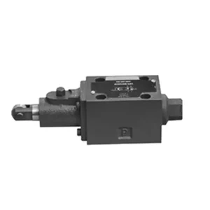
Η κατευθυντική υδραυλική βαλβίδα σειράς WMR με μηχανική, χειροκίνητη λειτουργία είναι μια πρωτοποριακή λύση σχεδιασμένη να παρέχει ακριβή έλεγχο σε υδραυλικά συστήματα. Αυτή η βαλβίδα προσφέρει βελτιωμένη απόδοση και ευελιξία με τα προηγμένα χαρακτηριστικά της και την στιβαρή κατασκευή της.
Η κατευθυντική υδραυλική βαλβίδα σειράς WMR με μηχανική, χειροκίνητη λειτουργία αποτελεί μια αξιόπιστη και ευέλικτη λύση για υδραυλικά συστήματα. Η αυτόματη και χειροκίνητη λειτουργία της και ο ακριβής κατευθυντικός έλεγχος προσφέρουν βελτιωμένη ευελιξία και έλεγχο για διάφορες εφαρμογές. Ακολουθώντας τις συνιστώμενες μεθόδους χρήσης και τηρώντας τις τακτικές πρακτικές συντήρησης, η βαλβίδα σειράς WMR θα συνεχίσει να παρέχει αποτελεσματική και αξιόπιστη λειτουργία. Αναβαθμίστε το υδραυλικό σας σύστημα με την κατευθυντική υδραυλική βαλβίδα σειράς WMR και απολαύστε τα οφέλη του βελτιωμένου ελέγχου και της ευελιξίας.
Κατευθυντική υδραυλική βαλβίδα σειράς WMR με μηχανική, χειροκίνητη λειτουργία Βασικά χαρακτηριστικά:
- Μηχανική, Χειροκίνητη λειτουργία:
- Η βαλβίδα της σειράς WMR διαθέτει μηχανική, χειροκίνητη λειτουργία, επιτρέποντας στους χειριστές να ελέγχουν τη θέση της βαλβίδας χειροκίνητα.
- Αυτό παρέχει ευελιξία και έλεγχο σε εφαρμογές όπου απαιτείται ή απαιτείται χειροκίνητη λειτουργία.
- Κατευθυντικός έλεγχος:
- Αυτή η υδραυλική βαλβίδα επιτρέπει τον ακριβή κατευθυντικό έλεγχο της ροής του ρευστού εντός του υδραυλικού συστήματος.
- Επιτρέπει στους χειριστές να επιλέξουν την επιθυμητή διαδρομή ροής, εξασφαλίζοντας αποτελεσματική και αξιόπιστη λειτουργία.
- Ανθεκτική κατασκευή:
- Η βαλβίδα σειράς WMR κατασκευάζεται με υλικά υψηλής ποιότητας, εξασφαλίζοντας ανθεκτικότητα και μακροζωία.
- Ο στιβαρός σχεδιασμός του μπορεί να αντέξει απαιτητικές συνθήκες λειτουργίας, παρέχοντας αξιόπιστη απόδοση.
- Ευρύ φάσμα εφαρμογών:
- Η βαλβίδα σειράς WMR ταιριάζει σε διάφορες βιομηχανίες και εφαρμογές, όπως η μεταποίηση, οι κατασκευές, η γεωργία κ.λπ.
- Μπορεί να χρησιμοποιηθεί σε υδραυλικά συστήματα που απαιτούν ακριβή και αποτελεσματικό έλεγχο ρευστού.
Κατευθυντική υδραυλική βαλβίδα σειράς WMR με μηχανική, χειροκίνητη λειτουργία Παράμετρος:
NG6
| Θέση εγκατάστασης | Προαιρετικός | ||
| Εύρος θερμοκρασίας ρευστού | ℃ | -30 έως +80 (σφραγίδες NBR) | |
| -20 έως +80 (σφραγίδες FKM) | |||
| Μέγιστη λειτουργούσα πίεση θυρών | Λιμάνι ABP | μπαρ | 315 |
| Λιμάνι Τ | μπαρ | 60 | |
| Μέγιστος ρυθμός ροής | Λ/λεπτό | 60 | |
| Διατομή ροής (εναλλαγή ουδέτερης θέσης) | Τύπος Q | χιλ.2 | Για το σύμβολο Q, 6% της ονομαστικής διατομής |
| Τύπος W | χιλ.2 | Για το σύμβολο W, 3% της ονομαστικής διατομής | |
| Υγρό | Ορυκτέλαιο· Φωσφορικός εστέρας | ||
| Εύρος ιξώδους | χιλ.2/μικρό | 2,8 έως 500 | |
| Βαθμός μόλυνσης | Μέγιστος επιτρεπόμενος βαθμός μόλυνσης υγρού: Κλάση 9. NAS 1638 ή 20/18/15, ISO4406 | ||
| Βάρος | κιλά | 1.4 | |
NG10
| Θέση εγκατάστασης | Προαιρετικός | ||
| Εύρος θερμοκρασίας ρευστού | ℃ | -30 έως +80 (σφραγίδες NBR) | |
| -20 έως +80 (σφραγίδες FKM) | |||
| Μέγιστη λειτουργούσα πίεση θυρών | Λιμάνι ABP | μπαρ | 315 |
| Λιμάνι Τ | μπαρ | 60 | |
| Μέγιστος ρυθμός ροής | Λ/λεπτό | 120 | |
| Διατομή ροής (εναλλαγή ουδέτερης θέσης) | Τύπος V | χιλ.2 | 11(A/B → T);10.3(P → A/B) |
| Τύπος W | χιλ.2 | 2.5 (A/B → T) | |
| Τύπος Q | χιλ.2 | 5.5 (A/B → T) | |
| Υγρό | Ορυκτέλαιο· Φωσφορικός εστέρας | ||
| Εύρος ιξώδους | χιλ.2/μικρό | 2,8 έως 500 | |
| Βαθμός μόλυνσης | Μέγιστος επιτρεπόμενος βαθμός μόλυνσης υγρού: Κλάση 9. NAS 1638 ή 20/18/15, ISO4406 | ||
| Βάρος | κιλά | 4 | |
Κατευθυντική υδραυλική βαλβίδα σειράς WMR με μηχανική, χειροκίνητη λειτουργία Πλεονεκτήματα:
• Βαλβίδα ολίσθησης άμεσης δράσης, βαλβίδα ολίσθησης άμεσης δράσης
• Ο τροχός κύλισης μπορεί να περιστραφεί κατά 90°
• Δεκαεννέα τυπικές λειτουργίες βαλβίδας ολίσθησης
Μέθοδος χρήσης κατευθυντικής υδραυλικής βαλβίδας σειράς WMR με μηχανική, χειροκίνητη λειτουργία:
- Ενσωμάτωση συστήματος:
- Προσδιορίστε την κατάλληλη θέση για τη βαλβίδα της σειράς WMR εντός του υδραυλικού συστήματος, λαμβάνοντας υπόψη την επιθυμητή κατεύθυνση ροής και τις απαιτήσεις ελέγχου.
- Βεβαιωθείτε για τη συμβατότητα με τις προδιαγραφές πίεσης και ροής του συστήματος.
- Τοποθετήστε τη βαλβίδα με ασφάλεια χρησιμοποιώντας κατάλληλες βάσεις ή αξεσουάρ στερέωσης.
- Συνδέσεις ρευστών:
- Επιλέξτε συμβατά υδραυλικά εξαρτήματα και εύκαμπτους σωλήνες για ασφαλείς και χωρίς διαρροές συνδέσεις.
- Ακολουθήστε τις οδηγίες του κατασκευαστή για τις σωστές τιμές ροπής κατά τη διαδικασία εγκατάστασης.
- Χρησιμοποιήστε κατάλληλα στεγανωτικά σπειρωμάτων ή ταινία για να εξασφαλίσετε αξιόπιστη σφράγιση.
- Χειροκίνητη λειτουργία:
- Εξοικειωθείτε με τον μηχανισμό χειροκίνητης λειτουργίας της βαλβίδας, συμπεριλαμβανομένου του μοχλού ή του κουμπιού που χρησιμοποιείται για τον έλεγχο της θέσης της βαλβίδας.
- Βεβαιωθείτε ότι ο χειριστής κατανοεί τη σωστή διαδικασία για τη χειροκίνητη ρύθμιση της θέσης της βαλβίδας.
- Βαθμονόμηση συστήματος:
- Βαθμονομήστε τη θέση και την κίνηση της βαλβίδας σύμφωνα με την επιθυμητή κατεύθυνση ροής και τις απαιτήσεις ελέγχου.
- Ρυθμίστε τη βαλβίδα χειροκίνητα για να επιτύχετε την επιθυμητή διαδρομή ροής και να διασφαλίσετε την ορθή λειτουργία.
Πώς να ρυθμίσετε τους υδραυλικούς ανυψωτήρες βαλβίδων;
Η ρύθμιση των υδραυλικών ανυψωτικών βαλβίδων είναι μια κρίσιμη εργασία συντήρησης για να διασφαλιστεί η σωστή απόδοση του κινητήρα και να αποφευχθούν προβλήματα όπως ο θόρυβος του συστήματος βαλβίδων και η μειωμένη ισχύς. Ακολουθεί ένας αναλυτικός οδηγός για τον τρόπο ρύθμισης των υδραυλικών ανυψωτικών βαλβίδων:
- Προετοιμασία του κινητήρα:
- Πριν ξεκινήσετε τη διαδικασία ρύθμισης, βεβαιωθείτε ότι ο κινητήρας είναι σβηστός και κρύος στην αφή.
- Αφαιρέστε τυχόν εξαρτήματα που είναι απαραίτητα για την πρόσβαση στα καλύμματα των βαλβίδων, όπως το συγκρότημα του φίλτρου αέρα ή τα καλώδια των μπουζί.
- Προσδιορίστε τη σωστή ακολουθία ρύθμισης βαλβίδας:
- Συμβουλευτείτε τις προδιαγραφές ή το εγχειρίδιο σέρβις του κατασκευαστή του κινητήρα για να προσδιορίσετε τη σωστή ακολουθία ρύθμισης βαλβίδων για τον συγκεκριμένο κινητήρα σας.
- Ορισμένοι κινητήρες έχουν μια σειρά ανάφλεξης που υπαγορεύει την ακολουθία, ενώ άλλοι έχουν συγκεκριμένες οδηγίες που βασίζονται στην αρίθμηση των κυλίνδρων.
- Εντοπίστε τη θέση του άνω νεκρού σημείου (TDC):
- Περιστρέψτε τον στροφαλοφόρο άξονα του κινητήρα στην κανονική κατεύθυνση περιστροφής μέχρι το έμβολο νούμερο ένα να φτάσει στη θέση άνω νεκρού σημείου (ΑΝΣ) κατά τη διαδρομή συμπίεσής του.
- Χρησιμοποιήστε ένα σημάδι χρονισμού στον αρμονικό εξισορροπητή ή στον σφόνδυλο και έναν δείκτη χρονισμού για να προσδιορίσετε με ακρίβεια τη θέση του ΑΝΣ.
- Ρύθμιση ανυψωτήρων βαλβίδων:
- Ξεκινήστε με τον πρώτο κύλινδρο στην ακολουθία ρύθμισης βαλβίδων.
- Αφαιρέστε το κάλυμμα της βαλβίδας για να έχετε πρόσβαση στα ζυγόθυρα και τους ανυψωτήρες βαλβίδων.
- Χαλαρώστε το παξιμάδι ασφάλισης στον βραχίονα του ζυγώθρου χρησιμοποιώντας ένα κατάλληλο κλειδί ή καρυδάκι.
- Γυρίστε τη βίδα ρύθμισης ή το μπουλόνι στο βραχίονα του ζυγώθρου δεξιόστροφα για να μειώσετε το διάκενο της βαλβίδας ή αριστερόστροφα για να το αυξήσετε.
- Ελέγξτε τις προδιαγραφές του κατασκευαστή του κινητήρα για το συνιστώμενο διάκενο βαλβίδων. Χρησιμοποιήστε ένα φίλερ για να μετρήσετε το διάκενο μεταξύ του ζυγώθρου και του στελέχους της βαλβίδας.
- Ρυθμίστε τον ανυψωτήρα βαλβίδας μέχρι να επιτευχθεί η σωστή απόσταση. Θα πρέπει να αισθανθείτε μια μικρή αντίσταση, αλλά θα μπορείτε να μετακινήσετε το φίλερ μπρος-πίσω.
- Κρατήστε τη βίδα ρύθμισης ή το μπουλόνι στη θέση της και σφίξτε καλά το παξιμάδι ασφάλισης.
- Επαναλάβετε τη διαδικασία:
- Μεταβείτε στον επόμενο κύλινδρο στην ακολουθία ρύθμισης βαλβίδων και επαναλάβετε τα βήματα 4 και 5 μέχρι να ρυθμιστούν όλοι οι ανυψωτήρες βαλβίδων.
- Επανατοποθετήστε τα καλύμματα βαλβίδων:
- Μόλις ολοκληρώσετε τη ρύθμιση των βαλβίδων σε όλους τους κυλίνδρους, τοποθετήστε ξανά τα καλύμματα των βαλβίδων και βεβαιωθείτε ότι είναι σωστά σφραγισμένα για να αποτρέψετε διαρροές λαδιού.
- Διπλός έλεγχος:
- Αφού ρυθμίσετε τους ανυψωτήρες βαλβίδων, συνιστάται να εκτελέσετε ξανά ολόκληρη την ακολουθία ρύθμισης βαλβίδων για να επιβεβαιώσετε ότι όλα τα διάκενα βρίσκονται εντός του καθορισμένου εύρους.
Ικανότητα & χωρητικότητα του εργοστασίου:
(1) Συναρμολόγηση
Διαθέτουμε μια πρώτης τάξεως ανεξάρτητη πλατφόρμα συναρμολόγησης έρευνας και ανάπτυξης. Το εργαστήριο παραγωγής υδραυλικών κυλίνδρων διαθέτει τέσσερις ημιαυτόματες γραμμές συναρμολόγησης ανυψωτικών κυλίνδρων και μία αυτόματη γραμμή συναρμολόγησης κυλίνδρων κλίσης, με σχεδιασμένη ετήσια παραγωγική ικανότητα 1 εκατομμυρίου τεμαχίων. Το εργαστήριο ειδικών κυλίνδρων είναι εξοπλισμένο με διάφορες προδιαγραφές ενός ημιαυτόματου συστήματος συναρμολόγησης καθαρισμού με σχεδιασμένη ετήσια παραγωγική ικανότητα 200.000 και εξοπλισμένο με διάσημο εξοπλισμό κατεργασίας CNC, ένα κέντρο κατεργασίας, έναν ειδικό εξοπλισμό επεξεργασίας κυλίνδρων υψηλής ακρίβειας, μια μηχανή συγκόλλησης ρομπότ, μια αυτόματη μηχανή καθαρισμού, μια αυτόματη μηχανή συναρμολόγησης κυλίνδρων και μια αυτόματη γραμμή παραγωγής βαφής. Υφιστάμενος κρίσιμος εξοπλισμός άνω των 300 σετ (σετ). Η βέλτιστη κατανομή και η αποτελεσματική χρήση των πόρων του εξοπλισμού διασφαλίζουν τις απαιτήσεις ακρίβειας των προϊόντων και καλύπτουν τις ανάγκες υψηλής ποιότητας των προϊόντων.


(2) Κατεργασία
Το εργαστήριο κατεργασίας είναι εξοπλισμένο με ένα προσαρμοσμένο κέντρο τόρνευσης με κεκλιμένη ράγα, κέντρο κατεργασίας, μηχανή λείανσης υψηλής ταχύτητας, ρομπότ συγκόλλησης και άλλο συναφή εξοπλισμό, το οποίο μπορεί να χειριστεί την επεξεργασία κυλινδρικών σωλήνων με μέγιστη εσωτερική διάμετρο 400 mm και μέγιστο μήκος 6 μέτρων.

(3) Συγκόλληση

(4) Βαφή και επίστρωση
Με μικρές και μεσαίες αυτόματες γραμμές επίστρωσης χρωμάτων με βάση το νερό, για την επίτευξη αυτόματης φόρτωσης και εκφόρτωσης ρομπότ και αυτόματου ψεκασμού, η ικανότητα σχεδιασμού 4000 τεμαχίων ανά βάρδια,
Διαθέτουμε επίσης μια ημιαυτόματη γραμμή παραγωγής χρωμάτων για μεγάλους κυλίνδρους που τροφοδοτείται από μια αλυσίδα ισχύος, με δυνατότητα σχεδιασμού 60 κιβωτίων ανά βάρδια.


(5) Δοκιμές
Διαθέτουμε πρώτης τάξεως εγκαταστάσεις επιθεώρησης και δοκιμαστικές κλίνες για να διασφαλίσουμε ότι η απόδοση του κυλίνδρου ανταποκρίνεται στις απαιτήσεις.

Είμαστε ένας από τους καλύτερους κατασκευαστές υδραυλικών κυλίνδρων. Μπορούμε να προσφέρουμε ολοκληρωμένους υδραυλικούς κυλίνδρους. Παρέχουμε επίσης αντίστοιχους γεωργικά κιβώτια ταχυτήτων. Έχουμε εξάγει τα προϊόντα μας σε πελάτες σε όλο τον κόσμο και έχουμε κερδίσει μια καλή φήμη λόγω της ανώτερης ποιότητας των προϊόντων μας και της εξυπηρέτησης μετά την πώληση. Καλωσορίζουμε τους πελάτες στο εσωτερικό και στο εξωτερικό να επικοινωνήσουν μαζί μας για να διαπραγματευτούν τις επιχειρήσεις, να ανταλλάξουν πληροφορίες και να συνεργαστείτε μαζί μας!


