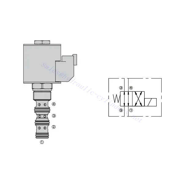
30SD10-40 Solenoid Directional Valve
30SD10-40 Solenoid Directional Valve
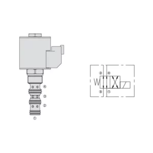
The 30SD10-40 solenoid directional valve is a high-performance industrial component designed to deliver precise and reliable fluid control in a variety of applications. With its advanced features, durable construction, and user-friendly design, this solenoid directional valve offers enhanced efficiency and operational reliability.
The 30SD10-40 solenoid directional valve is a reliable and versatile component that offers precise fluid control in industrial applications. Its robust construction, precision control, and reliable performance enhance efficiency and productivity in fluid control systems. By following the recommended usage methods and maintenance guidelines, you can ensure optimal performance and longevity of the 30SD10-40 solenoid directional valve in your industrial operations.
30SD10-40 Solenoid Directional Valve Characteristics:
- Robust Construction: The 30SD10-40 solenoid directional valve is built with exceptional craftsmanship and high-quality materials, ensuring durability and longevity. Its sturdy construction allows it to withstand demanding industrial environments, providing reliable performance even in harsh conditions.
- Versatile Functionality: This solenoid directional valve offers versatile functionality, making it suitable for a wide range of applications. It effectively controls the direction of fluid flow, enabling precise and efficient operation in various industrial systems.
- Precision Control: The 30SD10-40 solenoid directional valve provides exceptional precision in fluid control. It allows for accurate regulation and adjustment of fluid direction and pressure, ensuring optimal performance and efficiency in industrial processes.
- Reliable Performance: This solenoid directional valve delivers reliable performance, minimizing the risk of system failures or interruptions. It operates with dependability, contributing to increased productivity and reduced downtime in industrial operations.
30SD10-40 Solenoid Directional Valve Parameter:
| Presión nominal | 207 bar (3000 psi) | |
| Flujo máximo | 23 L/min (6 galones por minuto) | |
| Líquido | De base mineral o sintética con propiedades lubricantes | |
| Rango de temperatura ℃ | -54 a 107 ℃ (Sellos de poliuretano) | |
| -40 a 100 ℃ (sellos Buna N) | ||
| -26 a 204 ℃ (sellos de fluorocarbono) | ||
| Rango de viscosidad | 7,4 a 420 mm2/s | |
| Grado de contaminación | El nivel mínimo de contaminación es el nivel 20/18/14 de la norma ISO 4406, y se recomienda el nivel 17/15/13 para prolongar la vida útil. | |
| Fuga interna | ≤ 82 mL/min@207bar | |
| Cavidad | VC10-4 | |
| Clasificación de servicio de la bobina | Continua desde 85% hasta 115% de tensión nominal | |
| Consumo de corriente inicial de la bobina a 20 ℃ | Bobina electrónica | 1,7 A a 12 V CC; 0,85 A a 24 V CC |
| Bobina D | 1,67 A a 12 V CC; 0,83 A a 24 V CC | |
| Tensión mínima de entrada | 85% de potencia nominal a 207 bar | |
30SD10-40 Solenoid Directional Valve Advantages:
• Bobina con clasificación de servicio continuo
• Los cartuchos son intercambiables en voltaje.
• Bobinas E impermeables opcionales con clasificación hasta IP69K
• Construcción eficiente de armadura húmeda
• Cavidad común en la industria
• Piezas endurecidas para una larga vida útil
Usage Method Of 30SD10-40 Solenoid Directional Valve :
- Integration into the System: Integrate the 30SD10-40 Solenoid Directional Valve into the fluid control system following the manufacturer’s guidelines and specifications. Ensure proper alignment and connection between the valve and other system components to achieve optimal performance.
- Electrical Connection: Establish a secure electrical connection for the solenoid directional valve. Follow the provided wiring diagram and ensure correct polarity to prevent electrical malfunctions. Adhere to safety guidelines when working with electrical connections.
- Control de la dirección del flujo de fluidos: Utilice la válvula direccional solenoide para controlar la dirección del flujo de fluidos. La válvula suele estar equipada con una palanca o un actuador para el ajuste manual. También puede integrarse en un sistema de control automatizado para su operación remota.
- Pressure Adjustment: Use the solenoid directional valve to regulate fluid pressure within the system. Adjust the valve’s settings to achieve the desired pressure levels for optimal performance and efficiency.
How To Read Hydraulic Valve Schematics?
Reading hydraulic valve schematics requires a basic understanding of hydraulic symbols and their meanings. Here are the steps to help you read hydraulic valve schematics:
- Familiarize Yourself With Hydraulic Symbols: Hydraulic schematics use graphical symbols to represent various components and functions. Common symbols include squares for valves, lines for pipes or hoses, arrows for flow direction, and circles for pressure or flow control devices. Make sure you understand the meaning of these symbols before proceeding.
- Identify The Valve Types: Look for the valve symbols in the schematic. Valves can be represented by squares with different shapes and orientations. For example, a square with a diagonal line represents a check valve, while a square with an arrow inside denotes a directional control valve.
- Determine The Valve Function: Each valve symbol indicates its specific function. Directional control valves determine the flow direction of hydraulic fluid, while pressure control valves regulate pressure levels. Flow control valves manage the rate of fluid flow, and check valves allow flow in one direction only.
- Observe The Valve Connections: Pay attention to the lines or arrows entering and exiting the valve symbol. These lines represent the hydraulic fluid flow paths. Arrows indicate the flow direction, and lines connecting valves and other components indicate the connections.
- Analyze The Valve Ositions: Some hydraulic valve schematics include symbols to illustrate the valve positions. These symbols typically depict the valve spool or lever in different positions, such as open, closed, or partially open. Understanding the valve positions helps you determine the flow paths and the state of the hydraulic system.
- Consider Additional Symbols And Annotations: Hydraulic schematics may include additional symbols and annotations to indicate pressure gauges, flow meters, filters, accumulators, or other components. Familiarize yourself with these symbols and their meanings to gain a comprehensive understanding of the system.
- Follow The Flow Paths: Trace the flow paths from the hydraulic power source through the various valves and components to the actuator or desired output. Understand how the valves interact with one another and how they control fluid flow, pressure, and direction to achieve the desired system operation.
- Refer To The Legend Or Key: The schematic should have a legend or key that explains the meaning of each symbol used in the diagram. If you encounter unfamiliar symbols or have doubts about their meaning, refer to the legend for clarification.
- Seek Additional Resources If Needed: If you need a more in-depth understanding of hydraulic valve schematics, consider referring to hydraulic textbooks, online resources, or consulting with hydraulic experts who can provide guidance and explanations tailored to your specific needs.
Capacidad de la fábrica:
(1) Montaje
Contamos con una plataforma de ensamblaje independiente de primera clase para investigación y desarrollo. El taller de producción de cilindros hidráulicos cuenta con cuatro líneas de ensamblaje de cilindros de elevación semiautomáticos y una línea de ensamblaje de cilindros de inclinación automáticos, con una capacidad de producción anual diseñada de 1 millón de piezas. El taller de cilindros especiales está equipado con un sistema de ensamblaje de limpieza semiautomático de diversas especificaciones, con una capacidad de producción anual diseñada de 200,000 unidades, y está equipado con reconocidos equipos de mecanizado CNC, un centro de mecanizado, equipos especiales de procesamiento de cilindros de alta precisión, una máquina de soldadura robotizada, una máquina de limpieza automática, una máquina de ensamblaje de cilindros automáticos y una línea de producción de pintura automática. Contamos con más de 300 equipos críticos. La asignación óptima y el uso eficiente de los recursos de equipo garantizan la precisión y la alta calidad de los productos.


(2) Mecanizado
El taller de mecanizado está equipado con un centro de torneado de carril inclinado personalizado, un centro de mecanizado, una máquina de bruñido de alta velocidad, un robot de soldadura y otros equipos relacionados, que pueden procesar tubos cilíndricos con un diámetro interior máximo de 400 mm y una longitud máxima de 6 metros.

(3) Soldadura

(4) Pintura y revestimiento
Con pequeñas y medianas líneas de cilindros automáticos de recubrimiento de pintura a base de agua, para lograr la carga y descarga automática de robots y pulverización automática, la capacidad de diseño de 4000 piezas por turno;
También disponemos de una línea semiautomática de producción de pintura para grandes cilindros accionada por cadena, con una capacidad de diseño de 60 cajas por turno.


(5) Pruebas
Disponemos de instalaciones de inspección y bancos de pruebas de primera clase para garantizar que el rendimiento del cilindro cumple los requisitos.

Somos uno de los mejores fabricantes de cilindros hidráulicos. Ofrecemos cilindros hidráulicos integrales. También proporcionamos... cajas de cambios agrícolasHemos exportado nuestros productos a clientes de todo el mundo y nos hemos ganado una excelente reputación gracias a nuestra excelente calidad y servicio posventa. Invitamos a clientes nacionales e internacionales a contactarnos para negociar negocios, intercambiar información y... colabore con nosotros!