M-SR seeria hüdraulilise klapi kassett
M-SR seeria hüdraulilise klapi kassett
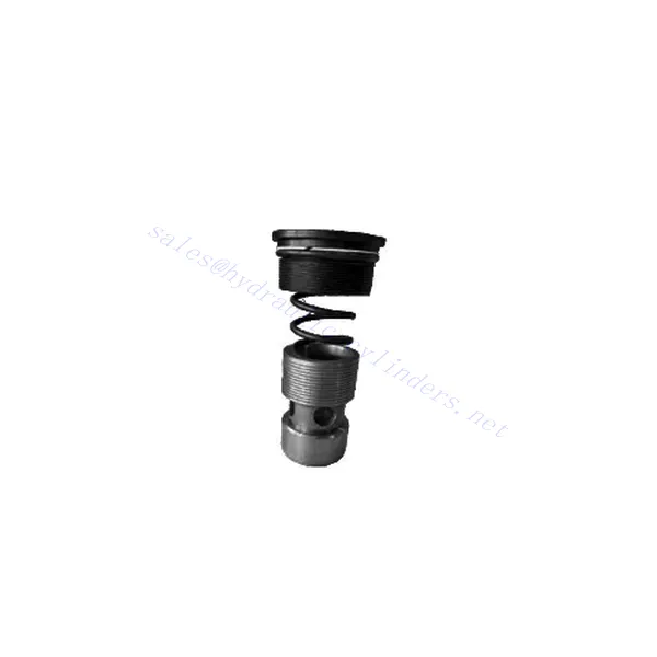
The M-SR series check hydraulic valve cartridge is versatile and essential in hydraulic systems. This valve cartridge is designed to regulate fluid flow and prevent backflow and offers reliable performance, durability, and ease of installation.
The M-SR series check hydraulic valve cartridge is a reliable and efficient solution for fluid control in hydraulic systems. With efficient check valve functionality, compact design, high flow capacity, and robust construction, this valve cartridge ensures optimal system performance, prevents backflow, and enhances overall efficiency. By following the recommended usage methods and maintenance practices, the M-SR series check hydraulic valve cartridge delivers reliable operation and extends the lifespan of hydraulic systems. Upgrade your hydraulic system with the m-sr series check hydraulic valve cartridge and experience efficient and reliable fluid control.
M-SR Series Check Hydraulic Valve Cartridge Key Characteristics:
- Efficient Check Valve Functionality:
- The M-SR series valve cartridge features a built-in check valve mechanism that enables the unidirectional flow of hydraulic fluid.
- It effectively prevents backflow and ensures fluid flows in the desired direction, minimizing the risk of system damage and inefficiency.
- Compact and Versatile Design:
- The valve cartridge is compact, making it suitable for applications with limited space or where weight considerations are crucial.
- Its versatile design allows easy integration into various hydraulic systems, including mobile machinery, industrial equipment, and hydraulic power units.
- Suur läbilaskevõime:
- Despite its compact size, the M-SR series valve cartridge offers high flow capacity, allowing for efficient fluid transfer and system performance.
- It minimizes pressure drops, ensuring optimal hydraulic power delivery to actuators and other components.
- Vastupidav konstruktsioon:
- Constructed from high-quality materials, the M-SR series valve cartridge demonstrates excellent durability and resistance to wear and corrosion.
- It is designed to withstand demanding operating conditions, prolonging the valve cartridge’s lifespan and reducing maintenance requirements.
M-SR Series Check Hydraulic Valve Cartridge Parameter:
| Spetsifikatsioonid | baar | NG6-30 | |||||
| Maksimaalne töörõhk | baar | 315 | |||||
| Pragunemisrõhk | baar | Vaadake karakteristiku kõverat | |||||
| Maksimaalne voolukiirus | L/min | Vaadake karakteristiku kõverat | |||||
| Viskoossusvahemik | mm2/s | 2.8 to 380 | |||||
| Vedeliku temperatuurivahemik | ℃ | -30 to +80(NBR seals) | |||||
| -20 to +80(FKM seals) | |||||||
| Vedelik | NBR- ja FKM-tihenditele sobiv mineraalõli | ||||||
| Fosfaatestrid FKM-tihendi jaoks | |||||||
| Saastumise aste | Vedeliku maksimaalne lubatud saastumisaste: klass 9. NAS 1638 või 20/18/15, ISO4406 | ||||||
| Suurus | 8 | 10 | 15 | 20 | 25 | 30 | |
| Weight: Right angled check valve cartridge | kg | 0.03 | 0.05 | 0.08 | 0.14 | 0.32 | 0.47 |
M-SR Series Check Hydraulic Valve Cartridge Advantages:
NG6-30
• Kasutatakse õliteede plokkide paigaldamisel
• Leak-free closure
• Various opening pressures available (see model description)
Usage Method Of M-SR Series Check Hydraulic Valve Cartridge:
- Süsteemianalüüs:
- Before installation, thoroughly analyze the hydraulic system to determine the specific requirements and operational parameters.
- Consider factors such as flow rates, pressure ratings, and compatibility with the M-SR series valve cartridge.
- Ventiili valik:
- Select the appropriate M-SR series valve cartridge variant based on the system requirements and specifications.
- Consider factors like flow capacity, pressure ratings, and compatibility with other system components.
- Paigaldamine:
- Follow the manufacturer’s instructions for properly installing the M-SR series valve cartridge in the hydraulic system.
- Ensure a secure fit within the valve cavity, proper alignment with the fluid flow path, and appropriate sealing to prevent leaks.
- Fluid Flow Direction:
- Ensure the M-SR Series Valve Cartridge is installed in the correct orientation, allowing for the desired fluid flow direction.
- Align the valve cartridge with the system’s flow path, ensuring proper engagement of the check valve mechanism.
How Does A Hydraulic Diverter Valve Work?
A hydraulic diverter valve is a key component in hydraulic systems that allows the operator to redirect hydraulic fluid flow from one path to another. It provides flexibility in controlling the flow direction and enables the use of multiple hydraulic actuators with a single hydraulic power source. Here’s a breakdown of how a hydraulic diverter valve works:
- Ventiili struktuur:
- A hydraulic diverter valve typically consists of a valve body with multiple ports, a movable spool or ball, and actuators such as levers, solenoids, or pilot pressure mechanisms.
- The valve body contains internal passages and chambers that direct the flow of hydraulic fluid.
- Vedeliku vooluteed:
- The diverter valve has multiple ports that connect to different hydraulic components in the system, such as the pump, reservoir, actuators, and other valves.
- These ports include an inlet port, outlet ports, and work ports, each serving a specific purpose in controlling the fluid flow.
- Spool or Ball:
- The valve body houses a movable spool or ball that controls the flow of hydraulic fluid.
- The spool can slide within the valve body, while the ball can rotate or move linearly to open or close specific passages.
- Käivitusmehhanismid:
- Hydraulic diverter valves can be actuated manually, electrically, or hydraulically, depending on the specific design and application requirement.
- Manual actuation involves levers or handles that the operator physically moves to position the spool or ball.
- Electrical actuation utilizes solenoids that receive electrical signals to shift the spool or ball, allowing for remote control and automation.
- Hydraulic actuation employs pilot pressure to move the spool or ball, often in conjunction with electrical or manual control.
- Ventiili asendid:
- Depending on the valve design, there are typically multiple positions that the spool or ball can assume, each corresponding to a specific flow path.
- Common positions include neutral, where all ports are blocked, and various actuating positions that allow flow between specific ports.
- As the spool or ball shifts, it aligns with specific ports, opening or closing passages and directing the hydraulic fluid accordingly.
- Operaatori sisend:
- The operator engages the hydraulic diverter valve by actuating the manual lever, applying electrical signals to solenoids, or manipulating pilot pressure.
- See sisend määrab soovitud klapi asendi, mis omakorda määrab voolu suuna ja hüdrauliliste ajamite töö.
- Süsteemi toimimine:
- Once the hydraulic diverter valve is in the desired position, hydraulic fluid flows through the appropriate passages and ports.
- This flow of fluid can be directed to different hydraulic actuators, allowing for selective control of the actuator’s movement or operation.
Tehase võimekus ja suutlikkus:
(1) Kokkupanek
Meil on esmaklassiline sõltumatu teadus- ja arendustegevuse montaažiplatvorm. Hüdrosilindrite tootmistöökojas on neli poolautomaatset tõstesilindrite koosteliini ja üks automaatne kallutussilindrite koosteliin, mille kavandatud aastane tootmisvõimsus on 1 miljon tükki. Spetsiaalsete silindrite töökoda on varustatud erinevate spetsifikatsioonidega poolautomaatse puhastusmontaažisüsteemiga, mille kavandatud aastane tootmisvõimsus on 200 000 ja mis on varustatud kuulsate CNC-töötlemisseadmete, mehaanilise töötlemise keskuse, suure täpsusega silindrite töötlemise eriseadmete, robotkeevitusmasina, automaatse puhastusmasina, automaatse silindri kokkupanemise masina ja automaatse värvimise tootmisliiniga. Olemasolevad kriitilised seadmed rohkem kui 300 komplekti (komplekti). Seadmete ressursside optimaalne jaotamine ja tõhus kasutamine tagavad toodete täpsusnõuded ja vastavad toodete kvaliteedinõuetele.


(2) Töötlemine
Töödeldav töökoda on varustatud kohandatud kallutatud rööpse treipingi keskuse, mehaanilise keskuse, kiire lihvimismasina, keevitusroboti ja muude seotud seadmetega, mis suudavad töödelda silindritorusid, mille maksimaalne siseläbimõõt on 400 mm ja maksimaalne pikkus on 6 meetrit.

(3) Keevitamine

(4) Värvimine ja katmine
Väikese ja keskmise suurusega silindri automaatse veepõhise värvipinnakattega liinide abil, et saavutada automaatne robotlaadimine ja mahalaadimine ning automaatne pihustamine, projekteerimisvõimsus 4000 tükki vahetuse kohta;
Meil on ka poolautomaatne suurte balloonide värvimise tootmisliin, mis töötab jõukettaga ja mille projekteerimisvõimsus on 60 kasti ühe vahetuse kohta.


(5) Testimine
Meil on esmaklassilised kontrolliseadmed ja katsestendid, et tagada silindri jõudlus vastavus nõuetele.

Oleme üks parimaid hüdrosilindrite tootjaid. Pakume laia valikut hüdrosilindreid. Pakume ka vastavaid... põllumajanduslikud käigukastid. Oleme eksportinud oma tooteid klientidele üle maailma ja teeninud hea maine tänu meie suurepärasele tootekvaliteedile ja müügijärgsele teenindusele. Me tervitame kliente kodus ja välismaal, et võtta meiega ühendust, et pidada läbirääkimisi äri, vahetada teavet ja teha meiega koostööd!


