
WMM-seeria suunaline hüdrauliline ventiil mehaanilise, käsitsi juhtimisega
WMM-seeria suunaline hüdrauliline ventiil mehaanilise, käsitsi juhtimisega
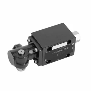
WMM-seeria mehaanilise käsitsi juhtimisega hüdrauliline suunaventiil on mitmekülgne ja usaldusväärne lahendus, mis on loodud hüdraulikasüsteemide täpseks juhtimiseks. See hüdrauliline ventiil pakub oma täiustatud funktsioonide ja vastupidava konstruktsiooniga suuremat efektiivsust ja paindlikkust.
WMM-seeria mehaanilise käsitsi juhtimisega hüdrauliline suunaventiil on usaldusväärne ja mitmekülgne lahendus hüdraulikasüsteemidele. Selle automaatne käsitsi juhtimine ja täpne suunajuhtimine pakuvad suuremat paindlikkust ja juhtimist erinevates rakendustes. Soovitatavate kasutusmeetodite ja regulaarsete hooldustavade järgimisel tagab WMM-seeria hüdrauliline ventiil jätkuvalt tõhusa ja usaldusväärse töö. Täiendage oma hüdraulikasüsteemi WMM-seeria suunaventiiliga ja kogege täiustatud juhtimise ja mitmekülgsuse eeliseid.
WMM-seeria suunaline hüdrauliline ventiil mehaanilise, käsitsi juhtimisega Põhiomadused:
- Mehaaniline, käsitsi juhtimine:
- WMM-seeria hüdrauliline klapp on mehaaniliselt käsitsi juhitav, mis võimaldab operaatoritel klapi asendit käsitsi juhtida.
- See pakub paindlikkust ja kontrolli rakendustes, kus on soovitav või vajalik käsitsi juhtimine.
- Suunakontroll:
- See hüdrauliline ventiil võimaldab hüdraulikasüsteemis vedeliku voolu täpset suunamist.
- See võimaldab operaatoritel valida soovitud voolutee, tagades tõhusa ja usaldusväärse töö.
- Vastupidav konstruktsioon:
- WMM-seeria hüdrauliline ventiil on valmistatud kvaliteetsetest materjalidest, mis tagab vastupidavuse ja pikaealisuse.
- Selle vastupidav disain talub nõudlikke töötingimusi, pakkudes usaldusväärset jõudlust.
- Kompaktne suurus:
- Ventiili kompaktne suurus võimaldab seda hõlpsalt integreerida piiratud ruumiga hüdraulikasüsteemidesse.
- See sobib ideaalselt rakenduste jaoks, kus ruum on piiratud, ilma et see kahjustaks jõudlust.
WMM-seeria suunaline hüdrauliline ventiil mehaanilise, käsitsi juhtimise parameetriga:
NG6
| Vedeliku temperatuurivahemik | ℃ | -30 kuni +80 (NBR-tihendid) | |
| -20 kuni +80 (FKM tihendid) | |||
| Port Max. töörõhk | Port ABP | baar | 315 |
| Sadam T | baar | 160 | |
| Maksimaalne voolukiirus | L/min | 60 | |
| Vooluala (neutraalse asendi vahetamine) | Q-tüüp | mm2 | Sümboli Q puhul on nimiristlõige 6% |
| W-tüüp | mm2 | Sümboli W puhul nimiristlõike 3% | |
| Vedelik | Mineraalõli; fosfaatester | ||
| Viskoossusvahemik | mm2/s | 2,8 kuni 500 | |
| Saastumise aste | Vedeliku maksimaalne lubatud saastumisaste: klass 9. NAS 1638 või 20/18/15, ISO4406 | ||
| Kaal | kg | 1.6 | |
NG10
| Vedeliku temperatuurivahemik | ℃ | -30 kuni +80 (NBR-tihendid) | |
| -20 kuni +80 (FKM tihendid) | |||
| Port Max. töörõhk | Port ABP | baar | 315 |
| Sadam T | baar | 160 | |
| Maksimaalne voolukiirus | L/min | 120 | |
| Voolu ristlõige (neutraalse asendi lülitamine) | V-tüüpi | mm2 | 11(A/B → T); 10,3(P → A/B) |
| W-tüüp | mm2 | 2,5 (A/B → T) | |
| Q-tüüp | mm2 | 5,5 (A/B → T) | |
| Vedelik | Mineraalõli; fosfaatester | ||
| Viskoossusvahemik | mm2/s | 2,8 kuni 500 | |
| Saastumise aste | Vedeliku maksimaalne lubatud saastumisaste: klass 9. NAS 1638 või 20/18/15, ISO4406 | ||
| Kaal | kg | 4.4 | |
NG16-32
| NS | 16 | 25 | 32 |
| Kaal | umbes 8 | umbes 12,2 | umbes 49 |
| Käivitusjõud fiksaatoriga N | umbes 75 | umbes 105 | umbes 170 |
| vedrutagastusega N | |||
| Käitusnurk neutraalasendi ümber | 2*26° | 2*32° | 2*30° |
| Max töörõhk Port A, B, P bar | 315 | ||
| T-pordi latt | 250 | ||
| Vedelik | NBR- ja FKM-tihenditele sobiv mineraalõli | ||
| Fosfaatester – FKM-tihendi jaoks | |||
| Vedeliku temperatuurivahemik | -30 kuni +80 (NBR-tihend) | ||
| -20 kuni +80 (FKM tihend) | |||
| Viskoossusvahemik mm2/s | 2,8 kuni 380 | ||
| Saastumise aste | Vedeliku maksimaalne lubatud saastumisaste: klass 9. NAS 1638 või 20/18/15, ISO4406 | ||
WMM-seeria suunahüdrauliline ventiil mehaanilise, käsitsi juhtimisega Eelised:
• Otsetoimeline suunaventiil otsetoimeline suunaventiil
• Alusplaadile kinnitamine
• Käepideme juhtimine
• Paigalduspind vastab standarditele DIN 24340 A ja ISO 4401
WMM-seeria suunalise hüdraulilise ventiili kasutusmeetod mehaanilise, käsitsi juhtimisega:
- Süsteemi integreerimine:
- Määrake WMM-seeria hüdraulilise klapi sobiv asukoht hüdraulikasüsteemis, arvestades soovitud voolusuunda ja juhtimisnõudeid.
- Veenduge, et see vastaks süsteemi rõhu- ja vooluspetsifikatsioonidele.
- Paigaldage ventiil kindlalt sobivate klambrite või kinnitustarvikute abil.
- Vedelikuühendused:
- Valige turvaliste ja lekkevabade ühenduste tagamiseks ühilduvad hüdraulilised liitmikud ja voolikud.
- Paigaldamise ajal järgige tootja juhiseid õigete pöördemomentide väärtuste kohta.
- Usaldusväärse tihendi tagamiseks kasutage sobivaid keermetihendeid või teipi.
- Käsitsi juhtimine:
- Tutvuge klapi käsitsi juhtimise mehhanismiga, sh hüdraulilise klapi asendi juhtimiseks kasutatava kangi või nupuga.
- Veenduge, et operaator mõistab klapi asendi käsitsi reguleerimise õiget protseduuri.
- Süsteemi kalibreerimine:
- Kalibreerige hüdraulilise klapi asend ja liikumine vastavalt soovitud voolusuunale ja juhtimisnõuetele.
- Soovitud voolutee saavutamiseks ja nõuetekohase toimimise tagamiseks reguleerige ventiili käsitsi.
Kuidas reguleerida hüdraulilise rull-nuki klappe?
Hüdraulilise rull-nukkide ventiilide reguleerimine nõuab hoolikat tähelepanu detailidele ja õige protseduuri järgimist. Siin on samm-sammult juhend, mis aitab teil ventiile õigesti reguleerida:
- Mootori ettevalmistamine:
- Enne reguleerimisprotsessi alustamist veenduge, et mootor on välja lülitatud ja puudutades jahtunud.
- Leidke klapikaaned ja eemaldage need, et pääseda ligi klapiajami komponentidele.
- Õige klapi reguleerimise järjekorra kindlakstegemine:
- Oma mootori jaoks õige klapi reguleerimise järjekorra määramiseks vaadake mootori tootja spetsifikatsioone või hooldusjuhendit.
- Ülemise surnud keskpunkti (TDC) asukoha leidmine:
- Pöörake mootori väntvõlli tavalises pöörlemissuunas, kuni esimene kolb jõuab oma survetakti ajal ülemisse surnud punkti.
- TDC asukoha täpseks määramiseks kasutage harmoonilise tasakaalustaja või hooratta ajastusmärki ja ajastusindikaatorit.
- Ventiili lõtku reguleerimine:
- Alustage klapi reguleerimise järjestuses esimesest silindrist.
- Keerake kiikvarda tihvti lukustusmutter sobiva mutrivõtme või pistikupesa abil lahti.
- Klapivarre ja klapivarre vahelise klapivahe (vahe) kontrollimiseks kasutage mootori tootja poolt soovitatud paksusega lehtrit.
- Lükake lehtrit klapihoova ja klapivarre vahele. Peaksite tundma kerget takistust, kuid lehtrit peaks siiski saama edasi-tagasi liigutada.
- Reguleerige klapivahe, pingutades või lõdvendades klapihoova tihvti, kuni saavutatakse õige vahe. Tihvti päripäeva keeramine vähendab vahet ja vastupäeva keeramine suurendab seda.
- Kui olete õige klapivahe seadnud, hoidke klapihoova tihvti paigal ja pingutage lukustusmutter kindlalt.
- Korrake protsessi:
- Liikuge ventiilide reguleerimise järjestuses järgmise silindri juurde ja korrake samme 4 ja 5, kuni kõik ventiilid on reguleeritud.
- Paigaldage klapikaaned tagasi:
- Kui olete kõigi silindrite ventiilide reguleerimise lõpetanud, paigaldage ventiilikaaned tagasi ja veenduge, et need oleksid õlilekete vältimiseks korralikult tihendatud.
- Topeltkontroll:
- Pärast ventiilide reguleerimist on hea tava kogu ventiilide reguleerimisjärjestus veel kord läbi käia, et veenduda, et kõik vahed on ettenähtud vahemikus.
Tehase võimekus ja suutlikkus:
(1) Kokkupanek
Meil on esmaklassiline sõltumatu teadus- ja arendustegevuse montaažiplatvorm. Hüdrosilindrite tootmistöökojas on neli poolautomaatset tõstesilindrite koosteliini ja üks automaatne kallutussilindrite koosteliin, mille kavandatud aastane tootmisvõimsus on 1 miljon tükki. Spetsiaalsete silindrite töökoda on varustatud erinevate spetsifikatsioonidega poolautomaatse puhastusmontaažisüsteemiga, mille kavandatud aastane tootmisvõimsus on 200 000 ja mis on varustatud kuulsate CNC-töötlemisseadmete, mehaanilise töötlemise keskuse, suure täpsusega silindrite töötlemise eriseadmete, robotkeevitusmasina, automaatse puhastusmasina, automaatse silindri kokkupanemise masina ja automaatse värvimise tootmisliiniga. Olemasolevad kriitilised seadmed rohkem kui 300 komplekti (komplekti). Seadmete ressursside optimaalne jaotamine ja tõhus kasutamine tagavad toodete täpsusnõuded ja vastavad toodete kvaliteedinõuetele.


(2) Töötlemine
Töödeldav töökoda on varustatud kohandatud kallutatud rööpse treipingi keskuse, mehaanilise keskuse, kiire lihvimismasina, keevitusroboti ja muude seotud seadmetega, mis suudavad töödelda silindritorusid, mille maksimaalne siseläbimõõt on 400 mm ja maksimaalne pikkus on 6 meetrit.

(3) Keevitamine

(4) Värvimine ja katmine
Väikese ja keskmise suurusega silindri automaatse veepõhise värvipinnakattega liinide abil, et saavutada automaatne robotlaadimine ja mahalaadimine ning automaatne pihustamine, projekteerimisvõimsus 4000 tükki vahetuse kohta;
Meil on ka poolautomaatne suurte balloonide värvimise tootmisliin, mis töötab jõukettaga ja mille projekteerimisvõimsus on 60 kasti ühe vahetuse kohta.


(5) Testimine
Meil on esmaklassilised kontrolliseadmed ja katsestendid, et tagada silindri jõudlus vastavus nõuetele.

Oleme üks parimaid hüdrosilindrite tootjaid. Pakume laia valikut hüdrosilindreid. Pakume ka vastavaid... põllumajanduslikud käigukastid. Oleme eksportinud oma tooteid klientidele üle maailma ja teeninud hea maine tänu meie suurepärasele tootekvaliteedile ja müügijärgsele teenindusele. Me tervitame kliente kodus ja välismaal, et võtta meiega ühendust, et pidada läbirääkimisi äri, vahetada teavet ja teha meiega koostööd!


