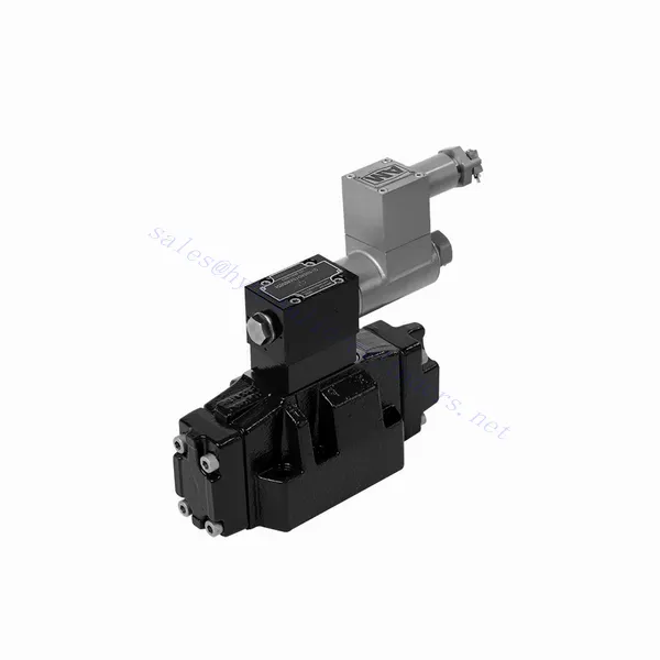
GWEH Series Explosion-proof Directional Hydraulic Valve
GWEH Series Explosion-proof Directional Hydraulic Valve
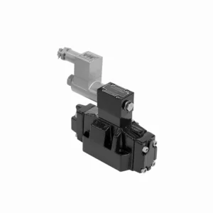
The GWEH series explosion-proof directional hydraulic valve is an innovative solution designed to provide optimal safety and precise control in hydraulic systems operating in hazardous environments. With its explosion-proof features, reliable performance, and advanced functionalities, this valve offers enhanced safety measures, efficient fluid flow control, and compatibility with various industrial applications.
The GWEH series explosion-proof directional hydraulic valve is a reliable and efficient solution for industries operating in hazardous environments. With its explosion-proof design, precise directional control, versatility, and high performance, this valve ensures safety and control in hydraulic systems. Following the recommended usage methods and adhering to regular maintenance practices, the GWEH series valve delivers safe and efficient operation in explosive atmospheres. Upgrade your hydraulic system with the GWEH series explosion-proof directional hydraulic valve and experience enhanced safety, optimal fluid flow control, and reliable performance.
GWEH Series Explosion-proof Directional Hydraulic Valve Key Characteristics:
- Räjähdyssuojattu rakenne:
- The GWEH series valve is engineered with a robust explosion-proof design, ensuring safe operation in environments containing flammable gases or dust.
- It complies with stringent safety standards and certifications, minimizing the risk of ignition and ensuring the safety of personnel and equipment.
- Suuntaohjaus:
- This hydraulic valve provides precise directional control of fluid flow, allowing for the activation and deactivation of specific hydraulic actuators.
- It enables smooth and reliable operation of various hydraulic functions, such as cylinder extension and retraction or motor direction changes.
- Monipuolisuus ja yhteensopivuus:
- The GWEH series valve is highly versatile and compatible with various hydraulic systems and applications.
- It can seamlessly integrate into industrial machinery, mobile equipment, and automation systems operating in hazardous environments.
- Korkea suorituskyky:
- With its advanced design and high-quality construction, the GWEH series hydraulic valve delivers exceptional performance and reliability.
- It ensures consistent and precise control over fluid flow, contributing to efficient and optimized system operation.
GWEH Series Explosion-proof Directional Hydraulic Valve Parameter:
NG10
| Working pressureP,A,B | baari | 315 | |||||||||
| Portti T | With external pilot oil drain | baari | 315 | ||||||||
| With internal pilot oil drain | baari | 210 | |||||||||
| Portti Y | With external pilot oil drain | baari | 210 | ||||||||
| Min. ohjauspaine | Ulkoisella ohjausöljyn syötöllä
Sisäisellä ohjausöljyn syötöllä (not apply to C, Z, F, G, H, P, T, V) |
baari | 3-position valve 10 | ||||||||
| Spring-return 2-position valve 10 | |||||||||||
| Hydraulic-return 2-position valve 7 | |||||||||||
| Sisäisellä ohjausöljyn syötöllä ( apply to C, Z, F, G, H, P, T, V) |
baari | 4.5 | |||||||||
| Max. control pressure | baari | 250 | |||||||||
| Neste | Mineraaliöljy, fosfaattiesteri | ||||||||||
| Nesteen lämpötila-alue | ℃ | -30 - +80 (NBR-tiivisteet | |||||||||
| -20 - +80 (FKM-tiivisteet) | |||||||||||
| Viskositeettialue | mm2/s | 2,8–500 | |||||||||
| Controlled quantity in commutating process | cm3 | 3-position valve 2.04 2-position valve 4.08 | |||||||||
| Switching times (= Valve switching time from the neutral position to the switched position)(DC ) | |||||||||||
| Control pressure | baari | 70 | 140 | 210 | 250 | ||||||
| 3-position valve | neiti | 65 | 60 | 55 | 50 | ||||||
| 2-position valve | neiti | 80 | 75 | 70 | 65 | ||||||
| Kytkentäajat (= venttiilin kytkentäaika kytketystä asennosta neutraaliasentoon) | |||||||||||
| 3-position valve | neiti | 30 | |||||||||
| 2-position valve | neiti | 35 | 40 | 30 | 35 | 25 | 30 | 20 | 25 | ||
| Flow of shortest switching time | L/min | noin 35 | |||||||||
| Asennusasento | HC, HD, HK, HZ and HY of hydraulic return shall be installed horizontally. The rest are arbitrary | ||||||||||
NG16
| Tekniset tiedot | G-..WEH16../6B2.. type | |||||||
| Working pressureP,A,B bar | 350 | |||||||
| Portti T | Ulkoisella ohjausöljyn tyhjennyspalkilla | 250 | ||||||
| Sisäisellä ohjausöljyn tyhjennyspalkilla | 210 | |||||||
| Hydraulic-centering 3-position valve With internal pilot oil drain is impossible | ||||||||
| Portti Y | Ulkoisella ohjausöljyn tyhjennyspalkilla | 210 | ||||||
| Min. ohjauspaine | With external pilot oil supply bar
With internal pilot oil supply bar |
3-position valve 14 | ||||||
| Jousipalautteinen 2-asentoinen venttiili 14 | ||||||||
| Hydraulic-return 2-position valve 14 | ||||||||
| Sisäisellä ohjausöljyn syötöllä ( apply to C、Z、F、G、H、P、T、V) bar |
When applying back pressure valve or the flow is large, enginery of spool valve is 4.5 bar as C、Z、F、G、H、P、T and V | |||||||
| Maks. ohjauspaine bar | 250 | |||||||
| Neste | Mineraaliöljy, fosfaattiesteri | |||||||
| Nesteen lämpötila-alue ℃ | -30 - +80 (NBR-tiivisteet | |||||||
| -20 - +80 (FKM-tiivisteet) | ||||||||
| Viscosity range mm2 /s 2 | 2,8–500 | |||||||
| Ohjausöljyn tilavuuden vaihtaminen | ||||||||
| -Spring-centering 3-position valve cm3 | 5.72 | |||||||
| -2-position valve cm3 | 11.45 | |||||||
| * Kytkentäajat (= venttiilin kytkentäaika neutraalista asennosta kytkettyyn asentoon) (AC ja DC) | ||||||||
| Ohjauspainepalkki | 50 | 150 | 250 | |||||
| – Spring-centering 3-position valve ms | 65 | 60 | 58 | |||||
| – 2-position valve ms | 65 | 55 | 50 | |||||
| *Kytkentäajat (= venttiilin kytkentäaika neutraalista asennosta kytkentäasentoon) | ||||||||
| – Spring-centering 3-position valve ms | 40 | |||||||
| – 2-position valve ms | 45 | 35 | 30 | |||||
| Asennusasento | C,D,K,Z,Y Type hydraulic-return valves are installed horizontally, the rest can be installed arbitrarily。 | |||||||
| Flow of shorter switching time L/min | noin 35 | |||||||
| Weight of the valve kg | about 10.6 | |||||||
NG25
| Tekniset tiedot | G-H-…WEH25../6B2… type | |||||||||
| Working pressureP,A,B bar | 350 | |||||||||
| Portti T | Ulkoisella ohjausöljyn tyhjennyspalkilla | 250 | ||||||||
| Sisäisellä ohjausöljyn tyhjennyspalkilla | 210 | |||||||||
| Hydraulic-centering 3-position valve With internal pilot oil drain is impossible | ||||||||||
| Portti Y | Ulkoisella ohjausöljyn tyhjennyspalkilla | 210 | ||||||||
| Min. ohjauspaine | With external pilot oil supply bar
With internal pilot oil supply bar |
Spring-centering 3-position valve 13 | ||||||||
| Hydraulic-centering 3-position valve 18 | ||||||||||
| Spring-return 2-position valve 13 | ||||||||||
| Hydraulic-return 2-position valve 18 | ||||||||||
| Sisäisellä ohjausöljyn syötöllä | When applying back pressure valve or the flow is large, enginery of spool valve is 4.5 bar as C、Z、F、G、H、P、T and V | |||||||||
| Maks. ohjauspaine bar | 250 | |||||||||
| Neste | Mineraaliöljy, fosfaattiesteri | |||||||||
| Nesteen lämpötila-alue ℃ | -30 - +80 (NBR-tiivisteet | |||||||||
| -20 - +80 (FKM-tiivisteet) | ||||||||||
| Viscosity range mm2 /s 2 | 2,8–500 | |||||||||
| Ohjausöljyn tilavuuden vaihtaminen | ||||||||||
| -Spring-centering 3-position valve cm3 | 14.2 | |||||||||
| -2-position valve cm3 | 28.4 | |||||||||
| * Kytkentäajat (= venttiilin kytkentäaika neutraalista asennosta kytkettyyn asentoon) (AC ja DC) | ||||||||||
| Ohjauspainepalkki | 50 | 140 | 210 | 250 | ||||||
| – Spring-centering 3-position valve ms | 85 | 75 | 70 | 65 | ||||||
| – 2-position valve ms | 160 | 130 | 120 | 105 | ||||||
| **Kytkentäajat (= venttiilin kytkentäaika neutraalista asennosta kytkentäasentoon) | ||||||||||
| – Spring-centering 3-position valve ms | 40 | |||||||||
| – 2-position valve ms | 125 | 100 | 90 | 80 | ||||||
| Asennusasento | C,D,K,Z,Y Type hydraulic-return valves are installed horizontally, the rest can be installed arbitrarily。 | |||||||||
| Flow of shorter switching time L/min | noin 35 | |||||||||
| Weight of the valve kg | about 19 | |||||||||
GWEH Series Explosion-proof Directional Hydraulic Valve Advantages:
• Directional valve directional the oil path by controlling the main spool
• WEH-sähköhydraulinen ohjaus
• Two-position four-way or three-position four-way
• Installation face follows DIN 24340 A, ISO 4401, and CETOP-RP 121H Sub-plate mounting connection
• Vaihda puola ilman öljyn vapautumista
Usage Method Of GWEH Series Explosion-proof Directional Hydraulic Valve :
- Vaarallisen alueen arviointi:
- Suorita perusteellinen vaarallisen alueen arviointi erityisten räjähdysturvallisten vaatimusten ja luokituksen määrittämiseksi.
- Määritä asianmukaiset turvatoimenpiteet ja varotoimet, joita tarvitaan määräysten noudattamiseksi.
- Venttiilin valinta:
- Select the GWEH Series Valve with the suitable specifications, considering factors such as pressure ratings, flow capacity, and voltage requirements.
- Varmista yhteensopivuus hydraulijärjestelmän ja tietyn vaarallisen ympäristön kanssa.
- Asennus:
- Follow the manufacturer’s instructions for proper installation of the GWEH Series Valve in the hydraulic system.
- Varmista tukeva kiinnitys ja asianmukaiset sähköliitännät noudattaen suositeltuja vääntömomentteja ja johdotusohjeita.
- Ohjaus ja aktivointi:
- Utilize the recommended control method, such as electrical signals or remote activation, to operate the GWEH Series Valve.
- Kytke venttiili sopivaan virtalähteeseen ja ohjausjärjestelmään toimitettujen kytkentäkaavioiden mukaisesti.
How Does A Hydraulic Control Valve Work?
A hydraulic control valve is a critical component in hydraulic systems that regulates the flow and direction of hydraulic fluid to control the operation of hydraulic actuators. It enables precise control over various hydraulic functions, such as extending or retracting cylinders, controlling motor speed and direction, or adjusting the flow rate of hydraulic fluid. Here’s an overview of how a hydraulic control valve works:
- Venttiilin rakenne:
- A hydraulic control valve typically consists of a valve body, spools or poppets, and various internal passages.
- The valve body contains inlet and outlet ports for fluid connection and chambers that direct the flow.
- The spools or poppets are movable elements within the valve body that control the flow paths and connect the appropriate ports.
- Flow Control:
- The hydraulic control valve regulates the flow of hydraulic fluid by opening and closing specific flow paths within the valve.
- The position of the spools or poppets determines which ports are connected and allows fluid to flow in the desired direction.
- Suuntaohjaus:
- Hydraulic control valves provide directional control by selectively connecting or blocking fluid flow to different hydraulic actuators.
- By adjusting the position of the spools or poppets, the valve determines which actuator receives fluid and in which direction it moves.
- Actuation Methods:
- Hydraulic control valves can be actuated using manual levers, mechanical linkages, solenoids, or pilot pressure control.
- Manual control valves are operated by moving the levers or handles to position the spools or poppets.
- Solenoid-controlled valves use electromagnetic coils to actuate the valve, allowing for remote or automated control.
- Control Modes:
- Hydraulic control valves offer different control modes, such as 2-way, 3-way, or 4-way control.
- A 2-way control valve controls flow in one direction, allowing or blocking fluid flow.
- A 3-way control valve has three ports and can control the flow between two ports while blocking the third.
- A 4-way control valve has four ports and can route fluid between two actuator ports while blocking the other two.
- Paineen kompensointi:
- Some hydraulic control valves are equipped with pressure compensation features to maintain a consistent flow rate despite changes in system pressure.
- These valves adjust the flow passages based on pressure differentials, allowing for precise control regardless of varying operating conditions.
- Feedback and Control Loops:
- Advanced hydraulic control valves may incorporate feedback mechanisms, such as position or pressure sensors, to provide feedback to a control system.
- This feedback enables closed-loop control, where the system can monitor and adjust the valve’s position or flow based on desired setpoints or operating conditions.
Tehtaan kapasiteetti ja kapasiteetti:
(1) Kokoonpano
Meillä on ensiluokkainen riippumaton tutkimus- ja kehitystyön kokoonpanoalusta. Hydraulisylinterien tuotantopajassa on neljä puoliautomaattista nostosylinterin kokoonpanolinjaa ja yksi automaattinen kallistussylinterin kokoonpanolinja, joiden suunniteltu vuotuinen tuotantokapasiteetti on 1 miljoona kappaletta. Erikoissylinterin työpaja on varustettu erilaisilla eritelmillä puoliautomaattisen puhdistusasennuksen kokoonpanojärjestelmällä, jonka suunniteltu vuotuinen tuotantokapasiteetti on 200 000, ja se on varustettu kuuluisilla CNC-työstölaitteilla, työstökeskuksella, korkean tarkkuuden sylinterin käsittelyyn tarkoitetuilla erityislaitteilla, robottihitsauskoneella, automaattisella puhdistuslaitteella, automaattisella sylinterin kokoonpanokoneella ja automaattisella maalaustuotantolinjalla. Olemassa olevat kriittiset laitteet yli 300 sarjaa (sarjaa). Laiteresurssien optimaalinen kohdentaminen ja tehokas käyttö varmistavat tuotteiden tarkkuusvaatimukset ja täyttävät tuotteiden laatuvaatimukset.


(2) Koneistus
Työstöpaja on varustettu räätälöidyllä kaltevalla kiskosorvauskeskuksella, työstökeskuksella, suurnopeus-hiontakoneella, hitsausrobotilla ja muilla vastaavilla laitteilla, joilla voidaan käsitellä sylinteriputkia, joiden sisähalkaisija on enintään 400 mm ja enimmäispituus on 6 metriä.

(3) Hitsaus

(4) Maalaus ja pinnoitus
Pienillä ja keskisuurilla sylinterin automaattisilla vesipohjaisilla maalipinnoituslinjoilla automaattisen robotin lastaus- ja purku- ja automaattisen ruiskutuksen saavuttamiseksi, suunnittelukapasiteetti on 4000 kappaletta vuorossa;
Meillä on myös puoliautomaattinen maalauslinja suurille sylintereille, joka toimii voimaketjulla ja jonka suunnittelukapasiteetti on 60 laatikkoa työvuorossa.


(5) Testaus
Meillä on ensiluokkaiset tarkastustilat ja testialustat, joilla varmistetaan, että sylinterin suorituskyky täyttää vaatimukset.

Olemme yksi parhaista hydraulisylintereiden valmistajista. Voimme tarjota kattavia hydraulisylintereitä. Tarjoamme myös vastaavia maatalousvaihteistotOlemme vieneet tuotteitamme asiakkaille maailmanlaajuisesti ja ansainneet hyvän maineen erinomaisen tuotelaadun ja huoltopalvelumme ansiosta. Toivotamme tervetulleeksi asiakkaat kotimaassa ja ulkomailla ottamaan meihin yhteyttä neuvotellakseen liiketoimista, vaihtaakseen tietoja ja tehdä yhteistyötä kanssamme!