L-LFA Series Directional Control Hydraulic Valve
L-LFA Series Directional Control Hydraulic Valve
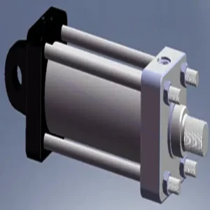
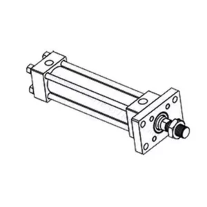
The L-LFA series directional control hydraulic valve is a cutting-edge component designed to deliver precise control and optimal performance in hydraulic systems. With its advanced features and robust construction, this valve provides reliable and efficient directional control for various applications.
The L-LFA series directional control hydraulic valve is a game-changer for hydraulic systems, offering precise directional control, versatility, and durability. By following the recommended usage methods and maintenance guidelines, you can harness the full potential of the L-LFA series valve and experience enhanced control, efficiency, and productivity in your hydraulic applications. Upgrade your hydraulic system today and unlock the advantages of precision and efficiency with the L-LFA series directional control hydraulic valve.
L-LFA Series Directional Control Hydraulic Valve Key Characteristics:
- Accurate Directional Control:
- The L-LFA series valve offers exceptional directional control, allowing precise and efficient management of fluid flow in hydraulic systems.
- This characteristic enables operators to direct hydraulic fluid to specific actuators or hydraulic components, facilitating smooth and controlled movement.
- Monipuoliset kokoonpanovaihtoehdot:
- This valve is available in various configurations, including 2-way, 3-way, and 4-way options, ensuring compatibility with diverse hydraulic system requirements.
- The 2-way configuration facilitates simple on/off control, while the 3-way and 4-way configurations enable more complex functions such as cylinder extension, retraction, and bi-directional control.
- High-Performance Construction:
- The L-LFA series valve is engineered with high-quality materials and precision manufacturing techniques to ensure durability and longevity.
- Its robust construction allows it to withstand high pressures, temperature variations, and harsh operating conditions, ensuring reliable performance even in demanding environments.
- Nopea vasteaika:
- This valve boasts an impressive response time, enabling rapid and efficient fluid flow control within the hydraulic system.
- The quick response time facilitates precise and immediate adjustments, resulting in enhanced system performance and reduced energy consumption.
L-LFA Series Directional Control Hydraulic Valve Parameter:
| Suurin käyttöpaine | Without directional valve | baari | 420 | |||||
| – Oil port A、B、X、Z1、Z2 | baari | 315; 350; 420(Depends on top-mounted directional valve) | ||||||
| – Oil port Y | baari | Equivalent to the return pressure of a top-mounted directional valve | ||||||
| Neste | Mineraaliöljy, joka sopii NBR- ja FKM-tiivisteille | |||||||
| Fosfaattiesteri FKM-tiivisteelle | ||||||||
| Nesteen lämpötila-alue | ℃ | -30 - +80 (NBR-tiiviste) | ||||||
| -20 - +80 (FKM-tiiviste) | ||||||||
| Viskositeettialue | mm2/s | 2,8–380 | ||||||
| Saastumisaste | Suurin sallittu nesteen kontaminaatioaste: Luokka 9. NAS 1638 tai 20/18/15, ISO4406 | |||||||
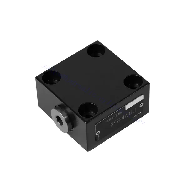
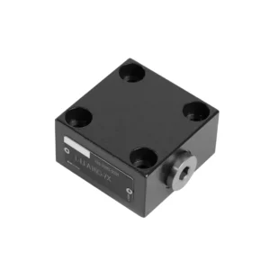
L-LFA Series Directional Control Hydraulic Valve Advantages:
• Basic type D with remote control
• With stroke limiter H
• Built-in shuttle valve G
• Built-in directional seat valve R, RF
• Can be equipped with directional valve WE
Usage Method Of L-LFA Series Directional Control Hydraulic Valve:
- Järjestelmän arviointi:
- Evaluate your hydraulic system and identify the specific directional control requirements.
- Determine whether the L-LFA series valve suits your system based on flow rates, pressure ratings, and compatibility with your application.
- Venttiilin valinta:
- Select the appropriate variant of the L-LFA series valve based on your system parameters and directional control needs.
- Consider factors such as valve type (2-way, 3-way, or 4-way), flow capacity, pressure rating, and compatibility with your specific application.
- Asennus:
- Noudata valmistajan asennusohjeita huolellisesti varmistaaksesi oikean kohdistuksen ja venttiilin turvallisen asennuksen.
- Käytä yhteensopivia hydrauliliittimiä, sovittimia ja tiivisteitä vuotamattomien liitosten muodostamiseksi. Kiristä liitokset riittävästi välttäen ylikiristämistä, joka voi vahingoittaa venttiiliä tai liittimiä.
- Järjestelmäintegraatio:
- Connect the hydraulic lines to the appropriate ports of the L-LFA series valve, ensuring the correct flow direction.
- Verify that the valve is installed in the correct orientation, as indicated by the directional arrows on the valve body.
- Käyttö ja ohjaus:
- Familiarize yourself with the control mechanisms of the L-LFA Series Valve, such as levers, knobs, or solenoids.
- Ensure that the valve is actuated correctly and that the desired hydraulic flow is achieved based on the system requirements.
Kuinka asentaa hydraulinen paineenalennusventtiili?
Hydraulisen paineenalennusventtiilin asentaminen on ratkaiseva vaihe hydraulijärjestelmän turvallisuuden ja moitteettoman toiminnan varmistamisessa. Tässä on vaiheittainen opas hydraulisen paineenalennusventtiilin asentamiseen:
- Tunnista venttiili: Määritä käyttämäsi hydraulisen paineenalennusventtiilin tyyppi ja malli. Varmista, että se sopii sovellukseesi ja on yhteensopiva hydraulijärjestelmäsi vaatimusten kanssa.
- Kerää tarvittavat työkalut ja materiaalit: Kerää tarvittavat työkalut ja materiaalit, mukaan lukien sopivat hydrauliliittimet, adapterit, jakoavaimet, teflonteippiä (kierteiden tiivistysaine) ja tarvittaessa painemittari. Katso valmistajan ohjeet tarvittavien työkalujen tai komponenttien osalta.
- Valmistele hydrauliikkajärjestelmä: Sammuta hydraulijärjestelmä ja vapauta paine aktivoimalla paineenalennusventtiili tai vetämällä hydraulisylintereitä sisään. Tämä vaihe on ratkaisevan tärkeä turvallisuuden kannalta ja estää tahattoman liikkeen tai hydraulinesteen vuotamisen.
- Paineenpoistokohdan tunnistaminen: Määritä hydraulisen paineenalennusventtiilin optimaalinen asennuspaikka hydraulijärjestelmässäsi. Se tulee sijoittaa pumpun alavirtaan ennen herkkiä komponentteja niiden suojaamiseksi liialliselta paineelta. Katso hydraulijärjestelmän kytkentäkaaviota tai kysy tarvittaessa ammattilaisen neuvoa.
- Asenna venttiili: Asenna hydraulinen paineenalennusventtiili tukevasti valittuun paikkaan käyttämällä sopivia kiinnikkeitä tai puristimia. Varmista, että venttiili on oikeassa asennossa ja että tulo- ja lähtöaukot ovat virtaussuunnan mukaiset. Noudata valmistajan ohjeita erityisten asennusvaatimusten osalta.
- Yhdistä tulo- ja lähtöportit: Kiinnitä hydrauliletkut tai -putket varoventtiilin tulo- ja lähtöportteihin. Käytä sopivia hydrauliliittimiä ja sovittimia vuotamattoman liitoksen luomiseksi. Levitä teflonteippiä tai kierretiivistettä liittimien uroskierteisiin varmistaaksesi turvallisen ja tiiviin liitoksen. Kiristä liitokset avaimilla vuotojen välttämiseksi, mutta varo kiristämästä liikaa.
- Aseta paineenpoistoasetus: Useimmissa hydraulisissa paineenalennusventtiileissä on säädettävä paineenalennusasetus. Säädä varoventtiili haluttuun paineenalennuspisteeseen valmistajan ohjeiden mukaisesti. Jotkin venttiilit saattavat vaatia painemittarin varopaineen tarkkaan asettamiseen. Asenna painemittari tarvittaessa väliaikaisesti ja säädä varoventtiiliä, kunnes haluttu paine on saavutettu.
- Testaa järjestelmä: Kun hydraulinen paineenalennusventtiili on asennettu, palauta hydraulijärjestelmän paine hitaasti. Tarkkaile painemittaria tai tarkkaile järjestelmän toimintaa varmistaaksesi, että varoventtiili toimii oikein. Varoventtiilin tulisi avautua ja ohjata ylipaine pois, kun se saavuttaa asetuspisteen, estäen järjestelmän vaurioitumisen.
- Seuranta ja ylläpito: Tarkasta hydraulinen paineenalennusventtiili säännöllisesti vuotojen, vaurioiden tai heikentyneen suorituskyvyn varalta. Puhdista venttiili ja sitä ympäröivä alue liasta ja roskista, jotka voivat vaikuttaa sen toimintaan. Noudata valmistajan suosittelemaa huolto-ohjelmaa ja -ohjeita optimaalisen suorituskyvyn ja pitkän käyttöiän varmistamiseksi.
Tehtaan kapasiteetti ja kapasiteetti:
(1) Kokoonpano
Meillä on ensiluokkainen riippumaton tutkimus- ja kehitystyön kokoonpanoalusta. Hydraulisylinterien tuotantopajassa on neljä puoliautomaattista nostosylinterin kokoonpanolinjaa ja yksi automaattinen kallistussylinterin kokoonpanolinja, joiden suunniteltu vuotuinen tuotantokapasiteetti on 1 miljoona kappaletta. Erikoissylinterin työpaja on varustettu erilaisilla eritelmillä puoliautomaattisen puhdistusasennuksen kokoonpanojärjestelmällä, jonka suunniteltu vuotuinen tuotantokapasiteetti on 200 000, ja se on varustettu kuuluisilla CNC-työstölaitteilla, työstökeskuksella, korkean tarkkuuden sylinterin käsittelyyn tarkoitetuilla erityislaitteilla, robottihitsauskoneella, automaattisella puhdistuslaitteella, automaattisella sylinterin kokoonpanokoneella ja automaattisella maalaustuotantolinjalla. Olemassa olevat kriittiset laitteet yli 300 sarjaa (sarjaa). Laiteresurssien optimaalinen kohdentaminen ja tehokas käyttö varmistavat tuotteiden tarkkuusvaatimukset ja täyttävät tuotteiden laatuvaatimukset.


(2) Koneistus
Työstöpaja on varustettu räätälöidyllä kaltevalla kiskosorvauskeskuksella, työstökeskuksella, suurnopeus-hiontakoneella, hitsausrobotilla ja muilla vastaavilla laitteilla, joilla voidaan käsitellä sylinteriputkia, joiden sisähalkaisija on enintään 400 mm ja enimmäispituus on 6 metriä.

(3) Hitsaus

(4) Maalaus ja pinnoitus
Pienillä ja keskisuurilla sylinterin automaattisilla vesipohjaisilla maalipinnoituslinjoilla automaattisen robotin lastaus- ja purku- ja automaattisen ruiskutuksen saavuttamiseksi, suunnittelukapasiteetti on 4000 kappaletta vuorossa;
Meillä on myös puoliautomaattinen maalauslinja suurille sylintereille, joka toimii voimaketjulla ja jonka suunnittelukapasiteetti on 60 laatikkoa työvuorossa.


(5) Testaus
Meillä on ensiluokkaiset tarkastustilat ja testialustat, joilla varmistetaan, että sylinterin suorituskyky täyttää vaatimukset.

Olemme yksi parhaista hydraulisylintereiden valmistajista. Voimme tarjota kattavia hydraulisylintereitä. Tarjoamme myös vastaavia maatalousvaihteistotOlemme vieneet tuotteitamme asiakkaille maailmanlaajuisesti ja ansainneet hyvän maineen erinomaisen tuotelaadun ja huoltopalvelumme ansiosta. Toivotamme tervetulleeksi asiakkaat kotimaassa ja ulkomailla ottamaan meihin yhteyttä neuvotellakseen liiketoimista, vaihtaakseen tietoja ja tehdä yhteistyötä kanssamme!