
WMM-sarjan mekaaninen ja manuaalinen hydraulinen suuntaventtiili
WMM-sarjan mekaaninen ja manuaalinen hydraulinen suuntaventtiili
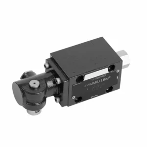
WMM-sarjan mekaanisella, manuaalisella ohjauksella varustettu hydraulinen suuntaventtiili on monipuolinen ja luotettava ratkaisu hydraulisten järjestelmien tarkkaan ohjaamiseen. Tämä hydraulinen venttiili tarjoaa parannetun tehokkuuden ja joustavuuden edistyneiden ominaisuuksiensa ja kestävän rakenteensa ansiosta.
WMM-sarjan mekaanisella, manuaalisella käytöllä varustettu hydraulinen suuntaventtiili on luotettava ja monipuolinen ratkaisu hydraulijärjestelmiin. Sen automaattinen manuaalinen käyttö ja tarkka suunnansäätö tarjoavat parannetun joustavuuden ja hallinnan erilaisissa sovelluksissa. Noudattamalla suositeltuja käyttötapoja ja säännöllisiä huoltokäytäntöjä WMM-sarjan hydraulinen venttiili toimii jatkossakin tehokkaasti ja luotettavasti. Päivitä hydraulijärjestelmäsi WMM-sarjan suuntaventtiilillä ja koe parannetun hallinnan ja monipuolisuuden edut.
WMM-sarjan mekaanisella, manuaalisella hydraulisella suuntaventtiilillä varustetut keskeiset ominaisuudet:
- Mekaaninen, manuaalinen käyttö:
- WMM-sarjan hydrauliventtiilissä on mekaaninen, manuaalinen käyttö, jonka avulla käyttäjät voivat säätää venttiilin asentoa manuaalisesti.
- Tämä tarjoaa joustavuutta ja hallintaa sovelluksissa, joissa manuaalinen käyttö on toivottavaa tai välttämätöntä.
- Suuntaohjaus:
- Tämä hydraulinen venttiili mahdollistaa tarkan ja suunnatun nestevirtauksen säädön hydraulijärjestelmässä.
- Sen avulla käyttäjät voivat valita halutun virtausreitin, mikä varmistaa tehokkaan ja luotettavan toiminnan.
- Kestävä rakenne:
- WMM-sarjan hydrauliventtiili on valmistettu korkealaatuisista materiaaleista, mikä takaa kestävyyden ja pitkän käyttöiän.
- Sen kestävä rakenne kestää vaativia käyttöolosuhteita ja tarjoaa luotettavan suorituskyvyn.
- Kompakti koko:
- Venttiilin kompakti koko mahdollistaa helpon integroinnin rajoitetusti tilaa vieviin hydraulijärjestelmiin.
- Se sopii erinomaisesti sovelluksiin, joissa tilaa on rajoitetusti, suorituskykyä vaarantamatta.
WMM-sarjan suuntaava hydraulinen venttiili mekaanisella, manuaalisella käyttöparametrilla:
NG6
| Nesteen lämpötila-alue | ℃ | -30 - +80 (NBR-tiivisteet) | |
| -20 - +80 (FKM-tiivisteet) | |||
| Portti Maks. käyttöpaine | Port ABP | baari | 315 |
| Portti T | baari | 160 | |
| Maks. virtausnopeus | L/min | 60 | |
| Virtausalue (kytkennän neutraali asento) | Q-tyyppi | mm2 | Symbolille Q, nimellispoikkileikkauksesta 6% |
| W-tyyppi | mm2 | Symbolille W, nimellispoikkileikkauksesta 3% | |
| Neste | Mineraaliöljy; Fosfaattiesteri | ||
| Viskositeettialue | mm2/s | 2,8–500 | |
| Saastumisaste | Suurin sallittu nesteen kontaminaatioaste: Luokka 9. NAS 1638 tai 20/18/15, ISO4406 | ||
| Paino | kg | 1.6 | |
NG10
| Nesteen lämpötila-alue | ℃ | -30 - +80 (NBR-tiivisteet) | |
| -20 - +80 (FKM-tiivisteet) | |||
| Portti Maks. käyttöpaine | Port ABP | baari | 315 |
| Portti T | baari | 160 | |
| Maks. virtausnopeus | L/min | 120 | |
| Virtauspoikkileikkaus (kytkennän neutraali asento) | V-tyyppi | mm2 | 11(A/B → T); 10,3(P → A/B) |
| W-tyyppi | mm2 | 2,5 (A/B → T) | |
| Q-tyyppi | mm2 | 5.5(A/B → T) | |
| Neste | Mineraaliöljy; Fosfaattiesteri | ||
| Viskositeettialue | mm2/s | 2,8–500 | |
| Saastumisaste | Suurin sallittu nesteen kontaminaatioaste: Luokka 9. NAS 1638 tai 20/18/15, ISO4406 | ||
| Paino | kg | 4.4 | |
NG16-32
| NS | 16 | 25 | 32 |
| Paino | noin 8 | noin 12,2 | noin 49 |
| Käyttövoima lukituksella N | noin 75 | noin 105 | noin 170 |
| jousipalautuksella N | |||
| Käyttökulma neutraaliasennon ympärillä | 2*26° | 2*32° | 2*30° |
| Maks. käyttöpaine, liitännät A, B, P, bar | 315 | ||
| Portin T-tanko | 250 | ||
| Neste | Mineraaliöljy, joka sopii NBR- ja FKM-tiivisteille | ||
| Fosfaattiesteri – FKM-tiivisteelle | |||
| Nesteen lämpötila-alue | -30 - +80 (NBR-tiiviste) | ||
| -20 - +80 (FKM-tiiviste) | |||
| Viskositeettialue mm2/s | 2,8–380 | ||
| Saastumisaste | Suurin sallittu nesteen kontaminaatioaste: Luokka 9. NAS 1638 tai 20/18/15, ISO4406 | ||
WMM-sarjan mekaanisen, manuaalisen hydraulisen suuntaventtiilin edut:
• Suoratoiminen suuntaventtiili suoratoiminen suuntaventtiili
• Aluslevyn kiinnitys
• Kahvaohjaus
• Asennuspinta standardien DIN 24340 A ja ISO 4401 mukaisesti
WMM-sarjan suuntaventtiilin käyttötapa mekaanisella, manuaalisella toiminnalla:
- Järjestelmäintegraatio:
- Määritä WMM-sarjan hydrauliventtiilin sopiva sijainti hydraulijärjestelmässä ottaen huomioon halutun virtaussuunnan ja ohjausvaatimukset.
- Varmista yhteensopivuus järjestelmän paine- ja virtausmääritysten kanssa.
- Kiinnitä venttiili tukevasti sopivilla kiinnikkeillä tai kiinnitystarvikkeilla.
- Nesteliitännät:
- Valitse yhteensopivat hydrauliliittimet ja letkut turvallisia ja vuotamattomia liitoksia varten.
- Noudata valmistajan ohjeita oikeiden vääntömomenttien varmistamiseksi asennuksen aikana.
- Käytä sopivia kierretiivisteitä tai teippiä luotettavan tiivistyksen varmistamiseksi.
- Manuaalinen käyttö:
- Tutustu venttiilin manuaaliseen käyttömekanismiin, mukaan lukien vipu tai nuppi, jota käytetään hydrauliventtiilin asennon ohjaamiseen.
- Varmista, että käyttäjä ymmärtää venttiilin asennon manuaalisen säädön oikean menettelyn.
- Järjestelmän kalibrointi:
- Kalibroi hydrauliventtiilin asento ja liike halutun virtaussuunnan ja ohjausvaatimusten mukaan.
- Säädä venttiiliä manuaalisesti halutun virtausreitin saavuttamiseksi ja oikean toiminnan varmistamiseksi.
Kuinka säätää venttiilejä hydraulisessa rullanokassa?
Hydraulisen rullanokka-akselin venttiilien säätö vaatii huolellista huomiota yksityiskohtiin ja oikean menettelyn noudattamista. Tässä on vaiheittainen opas venttiilien säätöön oikein:
- Valmistele moottori:
- Varmista, että moottori on sammutettu ja jäähtynyt ennen säätöprosessin aloittamista.
- Paikanna venttiilikopat ja irrota ne päästäksesi käsiksi venttiilikoneiston osiin.
- Tunnista oikea venttiilin säätöjärjestys:
- Tarkista moottorin valmistajan tiedoista tai huolto-oppaasta oikea venttiilien säätöjärjestys juuri sinun moottorillesi.
- Paikanna yläkuolokohta (TDC):
- Pyöritä moottorin kampiakselia normaaliin pyörimissuuntaan, kunnes mäntä numero yksi saavuttaa yläkuolokohdan puristusiskullaan.
- Käytä harmonisen tasapainottimen tai vauhtipyörän ajoitusmerkkiä ja ajoitusosoitinta yläkuolokohdan (TDC) tarkan määrittämiseen.
- Venttiilin välyksen säätö:
- Aloita venttiilien säätösekvenssin ensimmäisestä sylinteristä.
- Löysää keinuvivun tapin lukkomutteria sopivalla jakoavaimella tai hylsyavaimella.
- Tarkista venttiilivälys keinuvivun ja venttiilivarren välillä moottorin valmistajan suositteleman paksuisen rakotulkin avulla.
- Liu'uta rakotulkki keinuvivun ja venttiilin varren väliin. Sinun pitäisi tuntea pientä vastusta, mutta pystyä silti liikuttamaan mittaria edestakaisin.
- Säädä venttiilivälystä joko kiristämällä tai löysäämällä keinuvivun tappia, kunnes oikea välys on saavutettu. Tapin kiertäminen myötäpäivään pienentää välystä ja vastapäivään lisää sitä.
- Kun olet asettanut oikean venttiilivälyksen, pidä keinuvivun tappia paikallaan ja kiristä lukkomutteri tiukasti.
- Toista prosessi:
- Siirry venttiilien säätöjärjestyksessä seuraavaan sylinteriin ja toista vaiheet 4 ja 5, kunnes kaikki venttiilit on säädetty.
- Asenna venttiilikopat takaisin:
- Kun olet säätänyt kaikki sylinterit oikein, asenna venttiilikopat takaisin paikoilleen ja varmista, että ne ovat tiiviit öljyvuotojen estämiseksi.
- Tarkista vielä:
- Venttiilien säädön jälkeen on hyvä käytäntö käydä koko venttiilien säätösekvenssi läpi vielä kerran sen varmistamiseksi, että kaikki välykset ovat määritellyllä alueella.
Tehtaan kapasiteetti ja kapasiteetti:
(1) Kokoonpano
Meillä on ensiluokkainen riippumaton tutkimus- ja kehitystyön kokoonpanoalusta. Hydraulisylinterien tuotantopajassa on neljä puoliautomaattista nostosylinterin kokoonpanolinjaa ja yksi automaattinen kallistussylinterin kokoonpanolinja, joiden suunniteltu vuotuinen tuotantokapasiteetti on 1 miljoona kappaletta. Erikoissylinterin työpaja on varustettu erilaisilla eritelmillä puoliautomaattisen puhdistusasennuksen kokoonpanojärjestelmällä, jonka suunniteltu vuotuinen tuotantokapasiteetti on 200 000, ja se on varustettu kuuluisilla CNC-työstölaitteilla, työstökeskuksella, korkean tarkkuuden sylinterin käsittelyyn tarkoitetuilla erityislaitteilla, robottihitsauskoneella, automaattisella puhdistuslaitteella, automaattisella sylinterin kokoonpanokoneella ja automaattisella maalaustuotantolinjalla. Olemassa olevat kriittiset laitteet yli 300 sarjaa (sarjaa). Laiteresurssien optimaalinen kohdentaminen ja tehokas käyttö varmistavat tuotteiden tarkkuusvaatimukset ja täyttävät tuotteiden laatuvaatimukset.


(2) Koneistus
Työstöpaja on varustettu räätälöidyllä kaltevalla kiskosorvauskeskuksella, työstökeskuksella, suurnopeus-hiontakoneella, hitsausrobotilla ja muilla vastaavilla laitteilla, joilla voidaan käsitellä sylinteriputkia, joiden sisähalkaisija on enintään 400 mm ja enimmäispituus on 6 metriä.

(3) Hitsaus

(4) Maalaus ja pinnoitus
Pienillä ja keskisuurilla sylinterin automaattisilla vesipohjaisilla maalipinnoituslinjoilla automaattisen robotin lastaus- ja purku- ja automaattisen ruiskutuksen saavuttamiseksi, suunnittelukapasiteetti on 4000 kappaletta vuorossa;
Meillä on myös puoliautomaattinen maalauslinja suurille sylintereille, joka toimii voimaketjulla ja jonka suunnittelukapasiteetti on 60 laatikkoa työvuorossa.


(5) Testaus
Meillä on ensiluokkaiset tarkastustilat ja testialustat, joilla varmistetaan, että sylinterin suorituskyky täyttää vaatimukset.

Olemme yksi parhaista hydraulisylintereiden valmistajista. Voimme tarjota kattavia hydraulisylintereitä. Tarjoamme myös vastaavia maatalousvaihteistotOlemme vieneet tuotteitamme asiakkaille maailmanlaajuisesti ja ansainneet hyvän maineen erinomaisen tuotelaadun ja huoltopalvelumme ansiosta. Toivotamme tervetulleeksi asiakkaat kotimaassa ja ulkomailla ottamaan meihin yhteyttä neuvotellakseen liiketoimista, vaihtaakseen tietoja ja tehdä yhteistyötä kanssamme!


