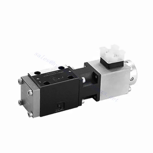
DBE6X(E) Series Proportional Pressure Relief Hydraulic Valve
DBE6X(E) Series Proportional Pressure Relief Hydraulic Valve
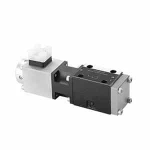
The DBE6X(E) series proportional pressure relief hydraulic Valve is a cutting-edge component that provides accurate and dynamic pressure control in hydraulic systems. With its advanced proportional control technology, this valve ensures optimal performance, efficiency, and safety.
The DBETX series proportional pressure relief hydraulic valve empowers hydraulic systems with precise pressure control, enhanced efficiency, and equipment protection. With its commensurate pressure relief capabilities, this valve ensures optimal performance across various applications. By following the recommended usage methods and maintenance guidelines, you can maximize the benefits and reliability of the DBETX series valve, elevating the performance and control of your hydraulic system. Upgrade your hydraulic setup today and experience superior pressure regulation with the DBETX series proportional pressure relief hydraulic valve.
DBE6X(E)-sarjan proportionaalisen paineenalennusventtiilin tärkeimmät ominaisuudet:
- Suhteellinen paineenalennus:
- The DBE6X(E) series valve offers precise and proportional pressure relief, allowing dynamic hydraulic pressure control.
- Se varmistaa tarkan paineensäädön vaihtelevissa kuormitusolosuhteissa, estäen järjestelmän ylikuormituksen ja suojaten hydrauliikkakomponentteja.
- Parannettu järjestelmän tehokkuus:
- Tämä venttiili mahdollistaa tarkan hydraulisen paineen säädön, mikä parantaa järjestelmän tehokkuutta ja vähentää energiankulutusta.
- Ylläpitämällä haluttuja painetasoja se minimoi paineenvaihtelut, optimoi järjestelmän suorituskyvyn ja alentaa käyttökustannuksia.
- Turvallisuus ja laitteiden suojaus:
- The DBE6X(E) Series Valve acts as a protective mechanism by limiting the pressure within the hydraulic system, safeguarding equipment and operators.
- Se estää liiallisen paineen muodostumisen, mikä vähentää komponenttien vaurioitumisen, järjestelmävikojen ja mahdollisten onnettomuuksien riskiä.
- Proportionaalinen ohjaustoiminto:
- With its proportional control technology, the DBE6X(E) series valve offers smooth and precise pressure adjustment.
- Se mahdollistaa reaaliaikaisen paineensäädön, mikä takaa saumattoman integroinnin erilaisiin hydraulijärjestelmiin ja sovelluksiin.
DBE6X(E) Series Proportional Pressure Relief Hydraulic Valve Parameter:
| Yleistä | ||||||
| Rakentaminen | Pilottivaihe | Lautasventtiili | ||||
| Päälava | Luistiventtiili | |||||
| Käyttö | Proportionaalinen solenoidi ilman asennon säätöä, ulkoinen vahvistin | |||||
| Yhteystyyppi | Pohjalevy, kiinnitysreiän kokoonpano NG6 (SIO 4401-03-02-094) | |||||
| Asennusasento | Valinnainen | |||||
| Olosuhteet lämpötila-alue | ℃ | -20 - +50 | ||||
| Paino | Kg | 2.2 | ||||
| Tärinänkestävyys, testiolosuhteet | Enintään 25 g, ravistettuna kolmessa suunnassa (24 h) | |||||
| Hydraulinen (mitattuna HLP 46:lla, öljy = 40 ℃ ± 5 ℃) : | ||||||
| Paineneste | Hydraulic oil to DIN 51524…535,other fluids after prior consultation | |||||
| Viskositeettialue | suositeltu | mm²/s | 20…100 | |||
| sallittu enimmäismäärä | mm²/s | 10…800 | ||||
| Painenesteen lämpötila-alue | ℃ | -20 - +80 | ||||
| Painenesteen suurin sallittu likaantumisaste Puhtausluokka standardin ISO 4406 (c) mukaisesti | Luokka 18/16/13 | |||||
| Virtaussuunta | Katso symboli | |||||
| Suurin asetuspaine (kun Qmaxx = 1 l/min) | baari | 80 | 180 | 250 | 315 | |
| Min. säädettävä paine(当 Qmin = 1 L/min) | baari | 7 | 8 | 9 | 10 | |
| Maks. käyttöpaine | baari | Portti P:315 | ||||
| Portti T:250 | ||||||
| Mekaanisen paineen enimmäisrajoitustaso, esim. kun solenoidin virta I>Imax | baari | < 90 | < 190 | < 260 | < 235 | |
| Ohjainöljyn virtaus | L/min | noin 0,6 | ||||
| Maks. virtausnopeus | L/min | 40 | ||||
| Sähkötiedot | ||||||
| Syklinen kestokerroin | % | 100 ED | ||||
| Suojausaste | IP 65 standardien DIN 40050 ja IEC 14434/5 mukaisesti | |||||
| Solenoidiliitäntä | Pistoliitin DIN 43650/ISO 4400 -standardin mukaisesti, M16X1.5 (2P+PE) | |||||
| Solenoidiventtiili | 0,8 A | 2,5 A | ||||
| Solenoidin maksimivirta | Imax | 0,8 A | 2,5 A | |||
| Käämin resistanssi R20 | Ω | 22 | 3 | |||
| Suurin virrankulutus 100%-kuormituksella ja käyttölämpötilassa | VA | 25 | 30 | |||
| Staattinen/Dynaaminen | ||||||
| Hystereesi | % | ≤ 4 | ||||
| Inversioalue | % | ≤3 | ||||
| Pmax-arvon valmistustoleranssi | % | ≤10 | ||||
| Vasteaika 100% signaalin muutoksessa | neiti | Päällä 200 / Pois päältä | ||||
DBE6X(E) Series Proportional Pressure Relief Hydraulic Valve Advantages:
• Järjestelmän paineen rajoittamiseen tarkoitettu ohjausventtiili (vain sisäinen ohjausöljy)
• Voidaan säätää ohjaamalla kelan virtaa ominaiskäyrän ja valitun elektronisen ohjausyksikön mukaisesti
• Solenoidityyppi Imax=0,8 A tai 2,5 A
• Elektronisen ohjausyksikön vikaantuessa ylikuormitussuoja voi toimia täydellä teholla (käämivirta > Imax)
• Käytetään venttiilin aluslevyn asennuksessa, asennusreikä on standardin ISO 441-03-02-0-94 mukainen
• Kaapeliliittimet ovat DIN 43650-AM2 -standardin mukaisia
• Ulkoinen elektroninen ohjausyksikkö, jossa ramppi- ja venttiilien säätötoiminto VT-SSPA1-508/525-L2X/V0/*
Usage Method Of DBE6X(E) Series Proportional Pressure Relief Hydraulic Valve:
- Järjestelmän arviointi:
- Arvioi hydrauliikkajärjestelmäsi ja määritä erityiset paineensäätövaatimukset.
- Determine if the DBE6X(E) series valve is compatible with your system based on its pressure range, flow capacity, and other specifications.
- Venttiilin valinta:
- Choose the appropriate DBE6X(E) series valve variant based on your system parameters, pressure range, and flow requirements.
- Ota huomioon suurin sallittu paineluokitus, vasteaika ja käyttöolosuhteet.
- Asennus:
- Noudata valmistajan asennusohjeita huolellisesti ja varmista venttiilin oikea kohdistus ja tukeva kiinnitys.
- Liitä venttiili hydraulijärjestelmään varmistaen vuotamattomat liitännät ja oikean virtaussuunnan kohdistuksen.
- Paineen säätö:
- Utilize the proportional control signal or adjustment mechanism provided with the DBE6X(E) series valve to set the desired pressure relief level.
- Säädä venttiiliä asteittain ja seuraa painemittarin lukemia ja järjestelmän vastetta tarkan paineensäädön saavuttamiseksi.
How To Adjust Hydraulic Flow Control Valve?
Adjusting a hydraulic pressure relief valve allows you to set the desired maximum pressure in a hydraulic system. This is important for maintaining system integrity and preventing damage to components. Here’s a step-by-step guide on how to adjust a hydraulic pressure relief valve:
- Tunnista paineenalennusventtiili:
- Locate the pressure relief valve in your hydraulic system. It is typically installed in the hydraulic line and often near the pump or control valve.
- Ymmärrä venttiilin suunnittelu:
- Tutustu käyttämäsi paineenalennusventtiilin erityiseen rakenteeseen. Eri venttiileissä voi olla erilaisia säätömekanismeja, kuten nuppi, ruuvi tai lukkomutteri.
- Determine the Desired Pressure:
- Assess the requirements of your hydraulic system and determine the desired maximum pressure. This will guide you in adjusting the pressure relief valve accurately.
- Valmistele järjestelmä:
- Ennen säätöjen tekemistä sammuta hydraulijärjestelmä ja vapauta paine siirtämällä ohjausvipuja edestakaisin tai noudattamalla valmistajan suosittelemia ohjeita.
- Paikanna säätömekanismi:
- Tunnista paineenalennusventtiilin säätömekanismi. Se voi olla nuppi, ruuvi tai lukkomutteri, joka sijaitsee venttiilin rungossa tai sen vieressä.
- Säädä venttiiliä:
- If the valve has a knob or handle, turn it clockwise to increase the pressure relief setting or counterclockwise to decrease it. If the valve has a screw, turn it clockwise to increase the pressure relief or counterclockwise to decrease it.
- Tee asteittaisia säätöjä:
- When adjusting the pressure relief valve, make small, incremental changes to avoid sudden or drastic variations in pressure. This allows you to fine-tune the maximum pressure and achieve the desired performance.
- Tarkkaile järjestelmää:
- With each adjustment, observe the hydraulic system and its components. Pay attention to the pressure gauge readings to see if they align with the desired maximum pressure.
- Testaa ja varmista:
- Operate the hydraulic system and monitor the pressure to ensure that it remains within the desired range. Check for any pressure fluctuations or irregularities that may indicate the need for further adjustment.
- Lukitse säätö:
- Once you have achieved the desired pressure relief setting, secure the adjustment mechanism to prevent unintended changes. Some valves may have a locking nut or set screw that can be tightened to hold the adjustment in place.
- Monitor and Revisit:
- Regularly monitor the pressure relief valve and the hydraulic system. If there are changes in the system or if the desired maximum pressure needs to be adjusted, revisit the pressure relief valve and repeat the adjustment process as needed.
Tehtaan kapasiteetti ja kapasiteetti:
(1) Kokoonpano
Meillä on ensiluokkainen riippumaton tutkimus- ja kehitystyön kokoonpanoalusta. Hydraulisylinterien tuotantopajassa on neljä puoliautomaattista nostosylinterin kokoonpanolinjaa ja yksi automaattinen kallistussylinterin kokoonpanolinja, joiden suunniteltu vuotuinen tuotantokapasiteetti on 1 miljoona kappaletta. Erikoissylinterin työpaja on varustettu erilaisilla eritelmillä puoliautomaattisen puhdistusasennuksen kokoonpanojärjestelmällä, jonka suunniteltu vuotuinen tuotantokapasiteetti on 200 000, ja se on varustettu kuuluisilla CNC-työstölaitteilla, työstökeskuksella, korkean tarkkuuden sylinterin käsittelyyn tarkoitetuilla erityislaitteilla, robottihitsauskoneella, automaattisella puhdistuslaitteella, automaattisella sylinterin kokoonpanokoneella ja automaattisella maalaustuotantolinjalla. Olemassa olevat kriittiset laitteet yli 300 sarjaa (sarjaa). Laiteresurssien optimaalinen kohdentaminen ja tehokas käyttö varmistavat tuotteiden tarkkuusvaatimukset ja täyttävät tuotteiden laatuvaatimukset.


(2) Koneistus
Työstöpaja on varustettu räätälöidyllä kaltevalla kiskosorvauskeskuksella, työstökeskuksella, suurnopeus-hiontakoneella, hitsausrobotilla ja muilla vastaavilla laitteilla, joilla voidaan käsitellä sylinteriputkia, joiden sisähalkaisija on enintään 400 mm ja enimmäispituus on 6 metriä.

(3) Hitsaus

(4) Maalaus ja pinnoitus
Pienillä ja keskisuurilla sylinterin automaattisilla vesipohjaisilla maalipinnoituslinjoilla automaattisen robotin lastaus- ja purku- ja automaattisen ruiskutuksen saavuttamiseksi, suunnittelukapasiteetti on 4000 kappaletta vuorossa;
Meillä on myös puoliautomaattinen maalauslinja suurille sylintereille, joka toimii voimaketjulla ja jonka suunnittelukapasiteetti on 60 laatikkoa työvuorossa.


(5) Testaus
Meillä on ensiluokkaiset tarkastustilat ja testialustat, joilla varmistetaan, että sylinterin suorituskyky täyttää vaatimukset.

Olemme yksi parhaista hydraulisylintereiden valmistajista. Voimme tarjota kattavia hydraulisylintereitä. Tarjoamme myös vastaavia maatalousvaihteistotOlemme vieneet tuotteitamme asiakkaille maailmanlaajuisesti ja ansainneet hyvän maineen erinomaisen tuotelaadun ja huoltopalvelumme ansiosta. Toivotamme tervetulleeksi asiakkaat kotimaassa ja ulkomailla ottamaan meihin yhteyttä neuvotellakseen liiketoimista, vaihtaakseen tietoja ja tehdä yhteistyötä kanssamme!