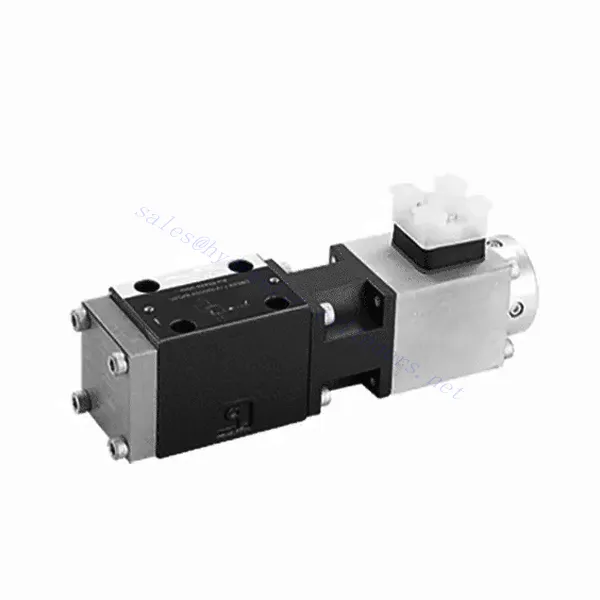
DBE6X(E) Series Proportional Pressure Relief Hydraulic Valve
DBE6X(E) Series Proportional Pressure Relief Hydraulic Valve
The DBE6X(E) series proportional pressure relief hydraulic Valve is a cutting-edge component that provides accurate and dynamic pressure control in hydraulic systems. With its advanced proportional control technology, this valve ensures optimal performance, efficiency, and safety.
The DBETX series proportional pressure relief hydraulic valve empowers hydraulic systems with precise pressure control, enhanced efficiency, and equipment protection. With its commensurate pressure relief capabilities, this valve ensures optimal performance across various applications. By following the recommended usage methods and maintenance guidelines, you can maximize the benefits and reliability of the DBETX series valve, elevating the performance and control of your hydraulic system. Upgrade your hydraulic setup today and experience superior pressure regulation with the DBETX series proportional pressure relief hydraulic valve.
DBE6X(E) Series Proportional Pressure Relief Hydraulic Valve Key Characteristics:
- Proportional Pressure Relief:
- The DBE6X(E) series valve offers precise and proportional pressure relief, allowing dynamic hydraulic pressure control.
- It ensures accurate pressure regulation in response to varying load conditions, preventing system overload and safeguarding hydraulic components.
- Verbeterde systeemefficiëntie:
- Deze klep maakt nauwkeurige regeling van de hydraulische druk mogelijk, wat resulteert in een hogere systeemefficiëntie en een lager energieverbruik.
- By maintaining the desired pressure levels, it minimizes pressure fluctuations, optimizes system performance, and reduces operational costs.
- Veiligheid en bescherming van apparatuur:
- The DBE6X(E) Series Valve acts as a protective mechanism by limiting the pressure within the hydraulic system, safeguarding equipment and operators.
- Het voorkomt overmatige drukopbouw, waardoor het risico op schade aan onderdelen, systeemstoringen en mogelijke ongelukken wordt verminderd.
- Functionaliteit voor proportionele regeling:
- With its proportional control technology, the DBE6X(E) series valve offers smooth and precise pressure adjustment.
- Het maakt realtime drukregeling mogelijk, waardoor naadloze integratie in diverse hydraulische systemen en toepassingen mogelijk is.
DBE6X(E) Series Proportional Pressure Relief Hydraulic Valve Parameter:
| Algemeen | ||||||
| Bouw | Pilotfase | Schotelklep | ||||
| Hoofdpodium | Spoelventiel | |||||
| Aandrijving | Proportionele solenoïde zonder positieregeling, externe versterker | |||||
| Verbindingstype | Onderplaat, montagegatconfiguratie NG6 (SIO 4401-03-02-094) | |||||
| Installatiepositie | Optioneel | |||||
| Omstandigheden temperatuurbereik | ℃ | -20 tot +50 | ||||
| Gewicht | kg | 2.2 | ||||
| Trillingsbestendigheid, testconditie | Max. 25 g, geschud in 3 dimensies (24 uur) | |||||
| Hydraulisch (gemeten met HLP 46, olie = 40℃ ±5℃): | ||||||
| Drukvloeistof | Hydraulic oil to DIN 51524…535,other fluids after prior consultation | |||||
| Viscositeitsbereik | aanbevolen | mm²/s | 20…100 | |||
| max. toegestaan | mm²/s | 10…800 | ||||
| Temperatuurbereik van de vloeistofdruk | ℃ | -20 tot +80 | ||||
| Maximaal toegestane verontreinigingsgraad van drukvloeistof Zuiverheidsklasse volgens ISO 4406 (c) | Klas 18/16/13 | |||||
| Stroomrichting | Zie symbool | |||||
| Maximale insteldruk (bij Qmaxx = 1 l/min) | bar | 80 | 180 | 250 | 315 | |
| Min. instelbare druk (当 Qmin = 1 l/min) | bar | 7 | 8 | 9 | 10 | |
| Maximale werkdruk | bar | Poort P: 315 | ||||
| Poort T: 250 | ||||||
| Maximale mechanische drukbegrenzing, bijvoorbeeld wanneer solenoïdestroom I>Imax | bar | < 90 | < 190 | < 260 | < 235 | |
| Pilotoliestroom | L/min | ongeveer 0,6 | ||||
| Max. debiet | L/min | 40 | ||||
| Elektrische gegevens | ||||||
| Cyclische duurfactor | % | 100 ED | ||||
| Beschermingsgraad | IP 65 volgens DIN 40050 en IEC 14434/5 | |||||
| Solenoïde aansluiting | Insteekconnector volgens DIN 43650/ISO 4400, M16X1.5(2P+PE) | |||||
| Klep met solenoïde type | 0,8A | 2,5A | ||||
| Max. solenoïdestroom | Imax | 0,8A | 2,5A | |||
| Spoelweerstand R20 | Ω | 22 | 3 | |||
| Maximaal stroomverbruik bij 100%-belasting en bedrijfstemperatuur | VA | 25 | 30 | |||
| Statisch/Dynamisch | ||||||
| Hysterese | % | ≤ 4 | ||||
| Bereik van inversie | % | ≤3 | ||||
| Productietolerantie voor Pmax | % | ≤10 | ||||
| Reactietijd 100% signaalverandering | mevrouw | Aan 200 / Uit | ||||
DBE6X(E) Series Proportional Pressure Relief Hydraulic Valve Advantages:
• Pilotklep om de systeemdruk te beperken (regelt alleen de interne olie)
• Kan worden aangepast door de spoelstroom te regelen volgens de karakteristieke curve en de geselecteerde elektronische regeleenheid
• Solenoïde type Imax=0,8 A of 2,5 A
• Bij uitval van de elektronische regeleenheid kan de overbelastingsbeveiliging optimaal functioneren (spoelstroom > Imax)
• Gebruikt bij montage op een klepsubplaat, het installatiegat voldoet aan ISO 441-03-02-0-94,
• Kabelaansluitingen volgens DIN 43650-AM2
• Externe elektronische regeleenheid met helling- en klepverstellingsfunctie VT-SSPA1-508/525-L2X/V0/*
Usage Method Of DBE6X(E) Series Proportional Pressure Relief Hydraulic Valve:
- Systeemevaluatie:
- Evalueer uw hydraulisch systeem en identificeer de specifieke vereisten voor drukregeling.
- Determine if the DBE6X(E) series valve is compatible with your system based on its pressure range, flow capacity, and other specifications.
- Klepselectie:
- Choose the appropriate DBE6X(E) series valve variant based on your system parameters, pressure range, and flow requirements.
- Houd rekening met de maximale druk, de reactietijd en de bedrijfsomstandigheden.
- Installatie:
- Volg de installatie-instructies van de fabrikant nauwkeurig op en zorg voor een juiste uitlijning en stevige montage van de klep.
- Sluit de klep aan op het hydraulische systeem en zorg ervoor dat er geen lekkage is en dat de stroomrichting correct is.
- Drukregeling:
- Utilize the proportional control signal or adjustment mechanism provided with the DBE6X(E) series valve to set the desired pressure relief level.
- Stel de klep stapsgewijs bij, onder controle van de drukmeterwaarden en de reactie van het systeem, om een nauwkeurige drukregeling te bereiken.
How To Adjust Hydraulic Flow Control Valve?
Adjusting a hydraulic pressure relief valve allows you to set the desired maximum pressure in a hydraulic system. This is important for maintaining system integrity and preventing damage to components. Here’s a step-by-step guide on how to adjust a hydraulic pressure relief valve:
- Identificeer het overdrukventiel:
- Locate the pressure relief valve in your hydraulic system. It is typically installed in the hydraulic line and often near the pump or control valve.
- Inzicht in het ontwerp van de klep:
- Maak uzelf vertrouwd met het specifieke ontwerp van de overdrukventiel waarmee u werkt. Verschillende ventielen kunnen verschillende afstelmechanismen hebben, zoals een knop, schroef of borgmoer.
- Determine the Desired Pressure:
- Assess the requirements of your hydraulic system and determine the desired maximum pressure. This will guide you in adjusting the pressure relief valve accurately.
- Het systeem voorbereiden:
- Voordat u aanpassingen maakt, dient u het hydraulische systeem uit te schakelen en de druk te verlagen door de bedieningshendels heen en weer te bewegen of door de door de fabrikant aanbevolen procedure te volgen.
- Zoek het afstelmechanisme:
- Identificeer het afstelmechanisme van de overdrukventiel. Dit kan een knop, schroef of borgmoer zijn, die zich op of vlakbij het ventielhuis bevindt.
- De klep afstellen:
- If the valve has a knob or handle, turn it clockwise to increase the pressure relief setting or counterclockwise to decrease it. If the valve has a screw, turn it clockwise to increase the pressure relief or counterclockwise to decrease it.
- Maak stapsgewijze aanpassingen:
- When adjusting the pressure relief valve, make small, incremental changes to avoid sudden or drastic variations in pressure. This allows you to fine-tune the maximum pressure and achieve the desired performance.
- Observeer het systeem:
- With each adjustment, observe the hydraulic system and its components. Pay attention to the pressure gauge readings to see if they align with the desired maximum pressure.
- Testen en verifiëren:
- Operate the hydraulic system and monitor the pressure to ensure that it remains within the desired range. Check for any pressure fluctuations or irregularities that may indicate the need for further adjustment.
- Vergrendel de afstelling:
- Once you have achieved the desired pressure relief setting, secure the adjustment mechanism to prevent unintended changes. Some valves may have a locking nut or set screw that can be tightened to hold the adjustment in place.
- Monitor and Revisit:
- Regularly monitor the pressure relief valve and the hydraulic system. If there are changes in the system or if the desired maximum pressure needs to be adjusted, revisit the pressure relief valve and repeat the adjustment process as needed.
Vermogen en capaciteit van de fabriek:
(1) Montage
We beschikken over een eersteklas, onafhankelijk R&D-platform voor assemblage. De productiewerkplaats voor hydraulische cilinders beschikt over vier semi-automatische hefcilinderassemblagelijnen en één automatische kantelcilinderassemblagelijn, met een geplande jaarlijkse productiecapaciteit van 1 miljoen stuks. De speciale cilinderwerkplaats is uitgerust met diverse specificaties van een semi-automatisch reinigingsassemblagesysteem met een geplande jaarlijkse productiecapaciteit van 200.000 stuks en is uitgerust met gerenommeerde CNC-bewerkingsapparatuur, een bewerkingscentrum, een zeer nauwkeurige cilinderbewerkingsapparatuur, een robotlasmachine, een automatische reinigingsmachine, een automatische cilinderassemblagemachine en een automatische verfproductielijn. De bestaande kritische apparatuur bestaat uit meer dan 300 sets. De optimale toewijzing en het efficiënte gebruik van apparatuur garanderen de nauwkeurigheidseisen van producten en voldoen aan de hoge kwaliteitseisen.


(2) Bewerking
De bewerkingsruimte is uitgerust met een op maat gemaakt schuin rails draaicentrum, bewerkingscentrum, hogesnelheids hoonmachine, lasrobot en andere bijbehorende apparatuur, die de bewerking van cilinderbuizen met een maximale binnendiameter van 400 mm en een maximale lengte van 6 meter aankan.

(3) Lassen

(4) Schilderen en coaten
Met kleine en middelgrote automatische cilindercoatinglijnen voor watergedragen verf, om automatisch laden en lossen door robots en automatisch spuiten te bereiken, is de ontwerpcapaciteit 4000 stuks per ploegendienst;
Ook beschikken wij over een semi-automatische verfproductielijn voor grote cilinders, aangedreven door een kabelrups, met een ontwerpcapaciteit van 60 dozen per ploeg.


(5) Testen
Wij beschikken over eersteklas inspectiefaciliteiten en testbanken om te garanderen dat de prestaties van de cilinder aan de eisen voldoen.

Wij zijn een van de beste fabrikanten van hydraulische cilinders. We bieden een compleet assortiment hydraulische cilinders. Ook leveren we bijbehorende onderdelen. landbouwversnellingsbakkenWe hebben onze producten wereldwijd geëxporteerd en een goede reputatie opgebouwd dankzij onze superieure productkwaliteit en aftersalesservice. We nodigen klanten in binnen- en buitenland uit om contact met ons op te nemen om zaken te doen, informatie uit te wisselen en werk met ons samen!