

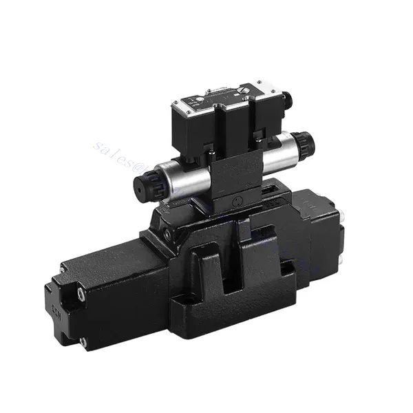
4WRZ/H(E) sorozatú, elővezérelt, proporcionális, irányított hidraulikus szelep

A 4WRZ/H(E) sorozatú, elővezérelt proporcionális irányított hidraulikus szelep egy csúcstechnológiás alkatrész, amelyet a hidraulikus rendszerek kivételes pontosságának, szabályozásának és hatékonyságának biztosítására terveztek. Fejlett, elővezérelt proporcionális szabályozási technológiájának köszönhetően ez a szelep pontos áramlásszabályozást és zökkenőmentes irányváltásokat tesz lehetővé.
A 4WRZ/H(E) sorozatú, elővezérelt proporcionális irányított hidraulikus szelep precíz áramlásszabályozással, sokoldalú irányváltásokkal és energiahatékonysággal ruházza fel a hidraulikus rendszereket. Az elővezérelt arányos szabályozási technológiája pontos és érzékeny áramlásszabályozást biztosít, míg a nagy áramlási kapacitás megbízható teljesítményt garantál még igényes alkalmazásokban is. Az ajánlott használati módszerek és karbantartási irányelvek betartásával maximalizálhatja a 4WRZ/H(E) sorozatú szelep előnyeit és hosszú élettartamát, új szintre emelve hidraulikus rendszerét a pontosság és a vezérlés terén. Frissítse hidraulikus rendszerét még ma, és tapasztalja meg a 4WRZ/H(E) sorozatú, elővezérelt proporcionális irányított hidraulikus szelep erejét.
4WRZ/H(E) sorozatú, elővezérelt, proporcionális, irányított hidraulikus szelep főbb jellemzői:
- Kísérletileg vezérelt arányos vezérlés
- A 4WRZ/H(E) sorozatú szelep elővezérelt arányos szabályozási technológiát alkalmaz, amely lehetővé teszi a vezérlőjelek alapján történő precíz és arányos áramlásszabályozást.
- Ez a funkció pontos és érzékeny vezérlést biztosít, ami jobb rendszerteljesítményt, alacsonyabb energiafogyasztást és fokozott termelékenységet eredményez.
- Sokoldalú irányvezérlés
- Ez a szelep sokoldalúan szabályozhatja a hidraulikus folyadék irányát, így széles körű alkalmazásokhoz alkalmas.
- Lehetővé teszi a hidraulikus alkatrészek, például hengerek, motorok és aktuátorok zökkenőmentes aktiválását és deaktiválását különböző irányokban, növelve a rendszer rugalmasságát és alkalmazkodóképességét.
- Nagy áramlási kapacitás
- A 4WRZ/H(E) sorozatú szelepet nagy áramlási sebesség kezelésére tervezték, így ideális olyan alkalmazásokhoz, amelyek jelentős hidraulikus teljesítményt igényelnek.
- Robusztus konstrukciója megbízható teljesítményt biztosít még nehéz körülmények között is, biztosítva az állandó és hatékony áramlásszabályozást.
- Energiahatékonyság
- Az elővezérelt arányos vezérlés beépítésével ez a szelep minimalizálja a nyomásesést és optimalizálja az energiafelhasználást.
- Segít csökkenteni az energiafogyasztást, ami költségmegtakarítást és környezeti előnyöket eredményez.
4WRZ/H(E) sorozatú, elővezérelt, arányos, irányított hidraulikus szelep paramétere:
| Általános | |||||||
| Szelep típusa | WRZ | WRZE | |||||
| Telepítés | Opcionális, lehetőleg vízszintes | ||||||
| Tárolási hőmérséklet-tartomány | ℃ | -20 és +80 között | |||||
| Környezeti hőmérsékleti tartomány | ℃ | -20 és +70 között | -20 és +50 között | ||||
| Súly | NS 10 | kg | 7.8 | 8 | |||
| NS 16 | kg | 13.4 | 13.6 | ||||
| NS 25 | kg | 18.2 | 18.4 | ||||
| NS 32 | kg | 42.2 | 42.4 | ||||
| Hidraulikus (HLPAG nyomócsővel mérve.p=100bar: 40 ℃ ± 5 ℃) | |||||||
| Méret | 10 | 16 | 25 | 32 | |||
| Üzemi nyomás | Vezérlőszelep | Külső pilot olajellátás | bár | 30-100 bar | |||
| Belső pilot olajellátás | bár | 100 to 350 with “D3” only | |||||
| Fő szelep | bár | 315-ig | 350-ig | 350-ig | 350-ig | ||
| Visszatérő nyomás | T csatlakozó (R csatlakozó) (külső elővezérelt olajleeresztő) | bár | 315-ig | 250-ig | 250-ig | 150-ig | |
| T csatlakozó (belső elővezérelt olajleeresztő) | bár | 30-ig | 30-ig | 30-ig | 30-ig | ||
| Y port | bár | 30-ig | 30-ig | 30-ig | 30-ig | ||
| Pilot olajmennyiség bemeneti jel 0-100 % | cm3 | 1.7 | 4.6 | 10 | 26.5 | ||
| Vezérlő olajáramlás az X és Y porton lépcsős bemeneti jellel 0-100 % | 3.5 | 5.5 | 7 | 15.9 | |||
| A fő szelep áramlása | L/perc | 170-ig | 460-ig | 870-ig | 1600-ig | ||
| Hidraulikafolyadék | L/perc | Ásványolaj (HL, HLP) DIN 51524 szerint További folyadékok érdeklődésre | |||||
| Hidraulikafolyadék hőmérsékleti tartománya | ℃ | -20 és +80 között (lehetőleg +40 és +50 között) | |||||
| Viszkozitási tartomány | mm2/s | 20-380 (lehetőleg 30-46) | |||||
| Szennyezettség mértéke | A nyomás alatti folyadék maximálisan megengedett szennyeződési foka a NAS 1638 vagy az ISO 4406(c) szabvány szerint van megadva. | Ajánlott egy legalább βx ≥ 75 visszatartási sebességű szűrő használata. | |||||
| Vezérlőszelep | NAS 1638 7. osztály | x=5 | |||||
| Fő szelep | NAS 1638 9. osztály | x=15 | |||||
| Hiszterézis | % | ≤6 | |||||
| Elektromos | |||||||
| Szelep típusa | WRZ | WRZE | |||||
| A szelep védelmi módja az EN 60529 szabvány szerint | IP65 felszerelt és reteszelt kábelcsatlakozóval | ||||||
| Feszültségtípus | DC | ||||||
| Parancsérték átfedés | % | 15 | |||||
| Max. áram | Egy | 1.5 | 2.5 | ||||
| Mágnesszelep tekercs ellenállása | Hidegérték 20 ℃-on | Ω | 4.8 | 2 | |||
| Max. melegítőérték | Ω | 7.2 | 3 | ||||
| Ciklikus időtartam-tényező | % | 100 | |||||
| Tekercs hőmérséklete | ℃ | 150-ig | |||||
| Szelepvédelem az EN 60529 szabvány szerint | IP65 | ||||||
| Vezérlő elektronika | |||||||
| Külső erősítő WRZ típushoz | VT- VSPA2-L2X/… | ||||||
| Parancsérték jel | -Voltage input “A1” | V. | ±10 | ||||
| –Current input “F1” | mA | 4-től 20-ig | |||||
4WRZ/H(E) sorozatú, elővezérelt, proporcionális, irányított hidraulikus szelep előnyei:
• Elővezérelt kétfokozatú proporcionális irányító szelep, amely a folyadékáramlás méretének és irányának szabályozására szolgál
• Menetes csatlakozású proporcionális mágnesszelep, a tekercs külön szétszerelhető
• Alsó lemezre szerelhető csatlakozószerkezet, a csatlakozó mérete megfelel a DIN2430 és ISO4401 szabványoknak
• Orsórugó beállításának beállítása
• WRZE típus integrált proporcionális erősítővel
• WRZ típusú külső erősítő (külön rendelendő)
A 4WRZ/H(E) sorozatú, pilotvezérelt, arányos, irányított hidraulikus szelep használati módja:
- Rendszerértékelés
- Értékelje a hidraulikus rendszerét, és határozza meg az áramlási és irányvezérlési követelményeket.
- Határozza meg, hogy a 4WRZ/H(E) sorozatú szelep alkalmas-e az áramlási kapacitása, a nyomásbesorolása és a rendszerrel való kompatibilitása alapján.
- Szelepválasztás
- Válassza ki a 4WRZ/H(E) sorozatú szelep megfelelő változatát a rendszerparaméterek, az áramlási követelmények és az irányvezérlési igények alapján.
- Vegyen figyelembe olyan tényezőket, mint a maximális áramlási sebesség, a nyomásbesorolás, a válaszidő és az üzemi feltételek.
- Telepítés
- Follow the manufacturer’s installation instructions carefully, ensuring proper alignment and secure mounting of the valve.
- A legjobb teljesítmény garantálása érdekében szivárgásmentes csatlakozásokat kell létrehozni, és biztosítani kell a megfelelő áramlási irányt.
- Vezérlőjel csatlakozás
- Csatlakoztassa a szelep vezérlőjel-vezetékeit egy megfelelő vezérlőeszközhöz, például proporcionális erősítőhöz vagy elektronikus vezérlőegységhez.
- A pontos és érzékeny szabályozás érdekében gondoskodjon a szelep és a vezérlőberendezés megfelelő bekötéséről és kompatibilitásáról.
Hogyan kell légteleníteni a hidraulikus vezérlőszelepet?
Bleeding a hydraulic control valve is an essential maintenance procedure to remove any trapped air or gas from the system, ensuring optimal performance and efficiency. Here’s a step-by-step guide on how to bleed a hydraulic control valve:
- A rendszer előkészítése:
- Győződjön meg arról, hogy a hidraulikus rendszer ki van kapcsolva, és hogy a nyomás mentesítve van. Ez a lépés elengedhetetlen a biztonsága és a nagynyomású folyadékok véletlen elmozdulásának vagy kiömlésének megakadályozása érdekében.
- Keresse meg a légtelenítő szelepet vagy a légtelenítő csavart a hidraulikus vezérlőszelepen. Ez jellemzően a szelepház tetején vagy oldalán található, és védősapkával vagy fedéllel is rendelkezhet.
- Elhelyezés és biztonsági intézkedések:
- Helyezzen egy megfelelő edényt vagy nedvszívó anyagot a légtelenítő szelep alá, hogy felfogja a légtelenítés során esetleg kilépő folyadékot.
- Viseljen megfelelő személyi védőfelszerelést (PPE), például védőszemüveget és kesztyűt, hogy megvédje magát a hidraulikafolyadék fröccsenésétől.
- A légtelenítő szelep kinyitása:
- Egy megfelelő villáskulcs vagy szerszám segítségével óvatosan lazítsa meg a légtelenítő szelepet vagy csavart az óramutató járásával ellentétes irányban. Vigyázzon, nehogy teljesen kicsavarja.
- A légtelenítő szelep rendelkezhet O-gyűrűvel vagy tömítő alátéttel. Figyelje meg a helyzetét, és győződjön meg róla, hogy jó állapotban van.
- Rendszer aktiválása:
- Aktiválja a hidraulikus rendszert az áramforrás, például egy motor vagy egy hidraulikus szivattyú bekapcsolásával.
- Működtesse a hidraulikus vezérlőszelephez tartozó vezérlőmechanizmust, például egy joystickot vagy kart, hogy a folyadék átáramoljon a szelepen.
- Vérzési folyamat:
- Lassan nyissa ki a légtelenítő szelepet az óramutató járásával ellentétes irányba forgatva, amíg hidraulikafolyadék vagy légbuborékok nem kezdenek távozni a szelepből.
- Hagyja a folyadékot néhány másodpercig folyni, vagy amíg egyenletes, légbuborékmentes folyadékáramot nem észlel. Ez azt jelzi, hogy a levegő távozott a rendszerből.
- Vigyázzon, ne nyissa ki túlságosan a légtelenítő szelepet, mert ez túlzott folyadékveszteséghez vagy a rendszer károsodásához vezethet.
- A légtelenítő szelep elzárása:
- Miután sikeresen légtelenítette a rendszert, zárja el a légtelenítő szelepet az óramutató járásával megegyező irányba forgatva. Győződjön meg róla, hogy biztonságosan meg van húzva, de ne húzza túl szorosra.
- Ellenőrizze, hogy nincs-e szivárgás a légtelenítő szelep vagy más csatlakozások körül. Ha bármilyen szivárgást észlel, azonnal javítsa ki a további problémák megelőzése érdekében.
- Rendszerellenőrzés:
- Kapcsolja ki a hidraulikus rendszert, és ellenőrizze a folyadékszintet a tartályban. Szükség szerint töltse fel a hidraulikafolyadékot az ajánlott szint fenntartásához.
- Ellenőrizze a hidraulikus vezérlőszelep és a kapcsolódó alkatrészek működését a megfelelő működés biztosítása érdekében.
A gyár kapacitása és kapacitása:
(1) Összeszerelés
Első osztályú független kutatási és fejlesztési összeszerelési platformmal rendelkezünk. A hidraulikus hengergyártó műhely négy félautomata emelőhenger-összeszerelő sorral és egy automata billenőhenger-összeszerelő sorral rendelkezik, tervezett éves gyártási kapacitása 1 millió darab. A speciális henger műhely különböző specifikációjú félautomata tisztító összeszerelő rendszerrel van felszerelve, amelynek tervezett éves termelési kapacitása 200.000, és híres CNC megmunkáló berendezéssel, megmunkáló központtal, nagy pontosságú hengerfeldolgozó speciális berendezéssel, robothegesztő géppel, automatikus tisztítógéppel, automatikus henger összeszerelő géppel és automatikus festési gyártósorral van felszerelve. A meglévő kritikus berendezések több mint 300 készlet (készlet). A berendezések erőforrásainak optimális elosztása és hatékony felhasználása biztosítja a termékek pontossági követelményeit és megfelel a termékek minőségi igényeinek.


(2) Megmunkálás
A megmunkálóműhely egyedi, ferde sínesztergáló központtal, megmunkálóközponttal, nagysebességű hónológéppel, hegesztőrobottal és egyéb kapcsolódó berendezésekkel van felszerelve, amelyek legfeljebb 400 mm belső átmérőjű és legfeljebb 6 méter hosszú hengercsövek megmunkálására képesek.


(3) Hegesztés


(4) Festés és bevonatolás
Kis és közepes méretű hengeres automatikus vízbázisú festékbevonó sorokkal, az automatikus robot be- és kirakodás, valamint az automatikus permetezés megvalósításához, a tervezési kapacitás műszakonként 4000 darab;
Rendelkezünk egy félautomata festékgyártósorral is nagyméretű palackokhoz, amelyet egy erőátviteli lánc hajt, műszakonként 60 doboz tervezési kapacitással.


(5) Tesztelés
Első osztályú ellenőrző létesítményekkel és tesztpadokkal rendelkezünk annak biztosítására, hogy a palack teljesítménye megfeleljen a követelményeknek.


Mi vagyunk az egyik legjobb hidraulikus henger gyártó. Átfogó hidraulikus hengereket kínálunk. Megfelelő szolgáltatásokat is biztosítunk. mezőgazdasági sebességváltókTermékeinket világszerte exportáltuk ügyfeleinknek, és kiváló termékminőségünknek és értékesítés utáni szolgáltatásunknak köszönhetően jó hírnevet szereztünk. Szeretettel várjuk belföldi és külföldi ügyfeleinket, hogy üzleti tárgyalások, információcsere és egyéb lehetőségek céljából kapcsolatba lépjenek velünk. együttműködni velünk!