50SD08-20 Solenoid Directional Valve
Mint a hidraulikus hengerek egyik gyártója, szállítója és exportőre a mechanikai termékek, kínálunk hidraulikus hengerek és sok más termék.
Kérjük, lépjen kapcsolatba velünk a részletekért.
Posta:sales@hydraulic-cylinders.net
Hidraulikus hengerek gyártója, szállítója és exportőre.
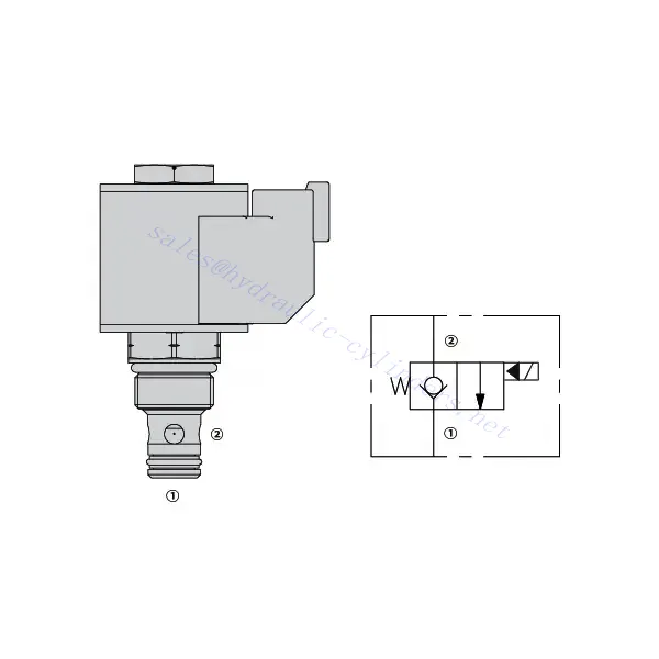
50SD08-20 Solenoid Directional Valve
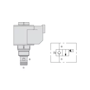
The 50SD08-20 solenoid directional valve is an advanced hydraulic component designed to provide precise control and efficient operation in a wide range of industrial applications. With its cutting-edge features, reliable performance, and robust construction, this valve offers an optimal solution for directing hydraulic fluid flow.
The 50SD08-20 solenoid directional valve offers enhanced control and efficient operation for hydraulic systems. With its versatile functionality, high flow capacity, quick response time, and robust construction, this valve provides optimal fluid flow control, enhancing system performance and productivity. By following the recommended usage methods and maintenance guidelines, you can maximize the potential of this valve and achieve improved efficiency in your hydraulic applications. Upgrade your hydraulic system today with the 50SD08-20 solenoid directional valve and experience enhanced control, reliability, and productivity.
50SD08-20 Solenoid Directional Valve Characteristics:
- Sokoldalú funkcionalitás:
- The 50SD08-20 solenoid directional valve offers versatile functionality, making it suitable for various hydraulic applications.
- Lehetővé teszi a folyadékáramlás pontos szabályozását, ami hatékony működést és jobb rendszerteljesítményt eredményez.
- Nagy áramlási kapacitás:
- Nagy áramlási kapacitásának köszönhetően ez a szelep jelentős folyadékmennyiségeket képes kezelni, így ideális választás nagy áramlási sebességet igénylő alkalmazásokhoz.
- A szelep nagy áramlási sebességek befogadására való képessége hatékony és megbízható működést biztosít, még igényes ipari környezetben is.
- Gyors válaszidő:
- A szelepbe épített mágnesszelep-technológia gyors válaszidőt biztosít, lehetővé téve a hidraulikafolyadék áramlásának gyors és pontos szabályozását.
- A gyors válaszidő növeli a rendszer hatékonyságát, és precíz beállításokat tesz lehetővé működés közben.
- Robusztus konstrukció:
- The 50SD08-20 solenoid directional Valve is built to withstand harsh operating conditions and provide long-lasting performance.
- Masszív konstrukciója és kiváló minőségű anyagai tartósságot biztosítanak, minimalizálják az állásidőt és csökkentik a karbantartási igényt.
50SD08-20 Solenoid Directional Valve Parameter:
| Névleges nyomás | 345 bar (5000 psi) | |
| Csúcsáramlás | Teljesítménydiagram megtekintése | |
| Folyadék | Ásványi alapú vagy szintetikus kenőanyagok | |
| Folyadékhőmérséklet-tartomány ℃ | -54–107 ℃ (poliuretán tömítések) | |
| -40 és 100 ℃ között (Buna N tömítések) | ||
| -26 és 204 ℃ között (fluorkarbon tömítések) | ||
| Viszkozitási tartomány | 7,4–420 mm2/s | |
| Szennyezettség mértéke | A minimális szennyezési szint ISO4406 18/16/13 szint, az élettartam meghosszabbítása érdekében pedig a 15/13/11 szint ajánlott. | |
| Belső szivárgás | ≤ 0.15 mL/min (3 drops/min) @ 345 bar | |
| Üreg | VC08-2 | |
| Tekercs üzemi besorolása | Folyamatos névleges feszültség 85%-től 115%-ig | |
| Kezdeti tekercsáram 20 ℃-on | 1,4 A 12 VDC feszültségnél; 0,7 A 24 VDC feszültségnél | |
| Minimális behúzási feszültség | 85% of nominal at 345 bar | |
50SD08-20 Solenoid Directional Valve Advantages:
• Folyamatos üzemű tekercs
• A hangszedők feszültség szerint cserélhetők
• Opcionális vízálló, akár IP69K besorolású E-tekercsek
• Ipari közös üreg
• Edzett alkatrészek a hosszú élettartam és az alacsony szivárgás érdekében
Usage Method Of 50SD08-20 Solenoid Directional Valve:
- Rendszerértékelés:
- Start by evaluating your hydraulic system’s requirements, including factors such as flow rate, pressure, and system dynamics.
- Determine if the 50SD08-20 Solenoid Directional Valve aligns with the specific needs of your system.
- Szelepválasztás:
- Select the appropriate variant of the 50SD08-20 Solenoid Directional Valve based on your system parameters and performance requirements.
- Az optimális működés érdekében vegyen figyelembe olyan tényezőket, mint az áramlási kapacitás, a nyomásbesorolás és a többi rendszerkomponenssel való kompatibilitás.
- Telepítés:
- A szelep megfelelő elhelyezéséhez és biztonságos rögzítéséhez gondosan kövesse a gyártó telepítési utasításait.
- Helyezze el helyesen a szelepet a hidraulikus rendszerben, figyelembe véve olyan tényezőket, mint a folyadékáramlás iránya és a karbantartáshoz való hozzáférés.
- Elektromos csatlakozások:
- Csatlakoztassa a mágnesszelepet a megfelelő áramforráshoz a gyártó előírásainak megfelelően.
- Győződjön meg arról, hogy az elektromos csatlakozások biztonságosak és megfelelnek a biztonsági előírásoknak.
How To Remove A Shower Valve Cartridge?
Removing a shower valve cartridge may vary depending on the specific model and manufacturer. However, here is a general step-by-step guide that can help you remove a shower valve cartridge:
- Turn off the Water Supply: Locate the main water shut-off valve for your shower and turn it off to cut off the water supply. This step is essential to prevent any water flow while you work on removing the cartridge.
- Remove the Shower Handle: Most shower handles have a screw or decorative cap at the base. Look for this screw or cap and remove it using a screwdriver or by gently prying it off. Once removed, take off the handle by pulling it straight out.
- Access the Cartridge: Depending on the type of shower valve you have, you may need to remove additional parts to access the cartridge. This can include a trim plate or escutcheon that covers the valve. Use a screwdriver to remove any screws holding these parts in place and gently pull them away.
- Remove the Retaining Clip or Nut: Look for a retaining clip or nut that holds the cartridge in place. This clip or nut is usually located on the top of the cartridge and secures it to the valve body. Use pliers or an adjustable wrench to loosen and remove the clip or nut.
- Remove the Cartridge: Once the retaining clip or nut is removed, you can proceed to pull out the cartridge. Grip the cartridge firmly and pull it straight out of the valve body. If it is stuck, you may need to wiggle it gently or use a cartridge removal tool specific to your shower valve model.
- Tisztítás és ellenőrzés: With the cartridge removed, take a moment to clean any debris or sediment from the valve body using a soft brush or cloth. Inspect the cartridge for any signs of damage or wear. If necessary, replace the cartridge with a new one that matches the model and make of your shower valve.
- Reassemble and Test: Once you have cleaned or replaced the cartridge, reassemble the shower valve by following the steps in reverse order. Make sure all parts are securely in place. Turn on the water supply and test the shower to ensure there are no leaks and that the new cartridge is functioning properly.
A gyár kapacitása és kapacitása:
(1) Összeszerelés
Első osztályú független kutatási és fejlesztési összeszerelési platformmal rendelkezünk. A hidraulikus hengergyártó műhely négy félautomata emelőhenger-összeszerelő sorral és egy automata billenőhenger-összeszerelő sorral rendelkezik, tervezett éves gyártási kapacitása 1 millió darab. A speciális henger műhely különböző specifikációjú félautomata tisztító összeszerelő rendszerrel van felszerelve, amelynek tervezett éves termelési kapacitása 200.000, és híres CNC megmunkáló berendezéssel, megmunkáló központtal, nagy pontosságú hengerfeldolgozó speciális berendezéssel, robothegesztő géppel, automatikus tisztítógéppel, automatikus henger összeszerelő géppel és automatikus festési gyártósorral van felszerelve. A meglévő kritikus berendezések több mint 300 készlet (készlet). A berendezések erőforrásainak optimális elosztása és hatékony felhasználása biztosítja a termékek pontossági követelményeit és megfelel a termékek minőségi igényeinek.


(2) Megmunkálás
A megmunkálóműhely egyedi, ferde sínesztergáló központtal, megmunkálóközponttal, nagysebességű hónológéppel, hegesztőrobottal és egyéb kapcsolódó berendezésekkel van felszerelve, amelyek legfeljebb 400 mm belső átmérőjű és legfeljebb 6 méter hosszú hengercsövek megmunkálására képesek.

(3) Hegesztés

(4) Festés és bevonatolás
Kis és közepes méretű hengeres automatikus vízbázisú festékbevonó sorokkal, az automatikus robot be- és kirakodás, valamint az automatikus permetezés megvalósításához, a tervezési kapacitás műszakonként 4000 darab;
Rendelkezünk egy félautomata festékgyártósorral is nagyméretű palackokhoz, amelyet egy erőátviteli lánc hajt, műszakonként 60 doboz tervezési kapacitással.


(5) Tesztelés
Első osztályú ellenőrző létesítményekkel és tesztpadokkal rendelkezünk annak biztosítására, hogy a palack teljesítménye megfeleljen a követelményeknek.

Mi vagyunk az egyik legjobb hidraulikus henger gyártó. Átfogó hidraulikus hengereket kínálunk. Megfelelő szolgáltatásokat is biztosítunk. mezőgazdasági sebességváltókTermékeinket világszerte exportáltuk ügyfeleinknek, és kiváló termékminőségünknek és értékesítés utáni szolgáltatásunknak köszönhetően jó hírnevet szereztünk. Szeretettel várjuk belföldi és külföldi ügyfeleinket, hogy üzleti tárgyalások, információcsere és egyéb lehetőségek céljából kapcsolatba lépjenek velünk. együttműködni velünk!
Hidraulikus henger alkalmazása:
