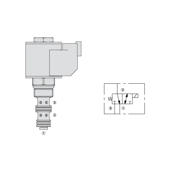
Katup Arah Solenoid 30SD08-30
Katup Arah Solenoid 30SD08-30
Experience unparalleled precision and control in your hydraulic system with the 30SD08-30 solenoid directional valve. This high-performance valve is designed to meet the demands of industrial applications, offering seamless fluid flow management and reliable operation.
The 30SD08-30 solenoid directional valve is a game-changer for hydraulic systems, offering precise control, high flow capacity, and rapid response time. With its durability and reliability, this valve guarantees optimal performance and efficiency. By following the recommended usage methods and maintenance guidelines, you can harness the full potential of the 30SD08-30 solenoid directional valve, achieving seamless control, increased productivity, and improved overall performance. Upgrade your hydraulic system today with the 30SD08-30 solenoid directional valve and experience the precision and reliability it brings to your operations.
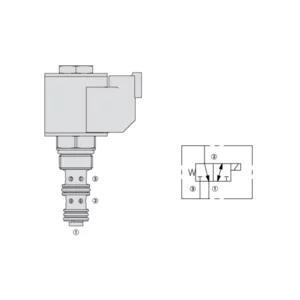
Karakteristik Katup Arah Solenoid 30SD08-26:
- Accurate Fluid Flow Control:
- The 30SD08-30 solenoid directional valve provides precise control over fluid flow, ensuring accurate and reliable operation of your hydraulic system.
- Experience seamless adjustments in flow rates, facilitating optimal performance in various industrial applications.
- Kapasitas Aliran Tinggi:
- With its high flow capacity design, the 30SD08-30 solenoid directional valve can handle substantial fluid volumes efficiently.
- This feature enables smooth and reliable operation, even in applications that require high flow rates, ensuring optimal system performance.
- Waktu Respon Cepat:
- Equipped with advanced solenoid technology, the 30SD08-30 solenoid directional valve boasts a rapid response time.
- Experience swift and accurate adjustments in fluid flow direction, allowing for enhanced system efficiency and precise control.
- Daya Tahan dan Keandalan:
- Built to withstand demanding operating conditions, the 30SD08-30 solenoid directional valve features a robust construction.
- Its durable materials and reliable design minimize downtime, reduce maintenance requirements, and ensure long-lasting performance.
Parameter Katup Arah Solenoid 30SD08-25:
| Tekanan terukur | 207 bar (3000 psi) |
| Aliran puncak | Lihat bagan kinerja |
| Cairan | Berbasis mineral atau sintetis dengan sifat pelumas |
| Kisaran suhu fluida ℃ | -54 hingga 107 ℃ (Segel poliuretan) |
| -40 hingga 100 ℃ (segel Buna N) | |
| -26 hingga 204 ℃ (Segel fluorokarbon) | |
| Kisaran viskositas | 7,4 hingga 420 mm2/S |
| Tingkat kontaminasi | Tingkat polusi minimum adalah level ISO4406 20/18/14, dan level 17/15/13 direkomendasikan untuk memperpanjang masa pakai |
| Kebocoran Internal | Port 3 (De-energized): ≤ 82 mL/min@207bar |
| Port 1 (Energized): ≤ 164 mL/min@207bar | |
| Rongga | VC08-3(Cavity variation ‘A’, see technical reference) |
| Peringkat Tugas Kumparan | Kontinu dari 85% hingga 115% tegangan nominal |
| Penarikan Arus Kumparan Awal pada 20℃ | 1,4A pada 12VDC; 0,7A pada 24VDC |
| Tegangan tarik minimum | 85% nominal pada 207 bar (3000 psi) |
Keunggulan Katup Arah Solenoid 30SD08-25:
• Kumparan dengan rating tugas kontinu
• Konstruksi rangka basah yang efisien
• Kartrid dapat dipertukarkan tegangannya
• E-Coil tahan air opsional dengan peringkat hingga IP69K
• Bagian yang diperkeras untuk umur panjang
Metode Penggunaan Katup Arah Solenoid 30SD08-25:
- Evaluasi Sistem:
- Begin by assessing the specific requirements of your hydraulic system, considering flow rates, pressure levels, and system dynamics.
- Evaluate if the 30SD08-30 Solenoid Directional Valve aligns with your system’s needs, taking into account its precision, flow capacity, and compatibility with other components.
- Pemilihan Katup:
- Select the appropriate variant of the 30SD08-30 solenoid directional valve based on your system parameters and performance requirements.
- Pertimbangkan faktor-faktor seperti kapasitas aliran, peringkat tekanan, dan kompatibilitas untuk memastikan integrasi yang mulus dan fungsionalitas yang optimal.
- Instalasi:
- Ikuti petunjuk pemasangan dari pabriknya dengan saksama untuk memastikan penempatan yang tepat dan pemasangan katup yang aman.
- Posisikan katup dengan benar dalam sistem hidrolik, pertimbangkan arah aliran fluida dan aksesibilitas untuk tujuan pemeliharaan.
- Sambungan Listrik:
- Hubungkan katup solenoid ke sumber daya yang ditentukan sesuai dengan spesifikasi pabrik.
- Pastikan sambungan listrik aman, mematuhi standar dan pedoman keselamatan.
Bagaimana Cara Memasang Katup Kontrol Aliran Hidrolik?
Untuk memasang katup kontrol aliran hidrolik, ikuti langkah-langkah berikut:
- Identifikasi Jenis Katup: Tentukan jenis katup kontrol aliran yang Anda gunakan. Jenis yang umum digunakan antara lain katup jarum, katup kontrol aliran yang dapat disesuaikan, atau katup kontrol aliran dengan kompensasi tekanan. Pastikan katup tersebut sesuai dengan aplikasi Anda dan kompatibel dengan sistem hidrolik Anda.
- Kumpulkan Alat dan Bahan yang Diperlukan: Kumpulkan peralatan dan bahan yang diperlukan, termasuk perlengkapan hidrolik, adaptor, selang, dan kunci pas yang sesuai.
- Siapkan Sistem Hidrolik: Matikan sistem hidrolik dan kurangi tekanan dalam sistem dengan mengaktifkan katup pelepas atau menarik silinder hidrolik. Langkah ini penting untuk keselamatan.
- Identifikasi Arah Aliran: Identifikasi arah aliran dalam sistem hidrolik Anda. Biasanya, arah aliran ditunjukkan oleh tanda panah pada komponen hidrolik. Pastikan Anda memahami arah aliran yang benar sebelum melanjutkan.
- Temukan Titik Instalasi: Tentukan lokasi optimal untuk memasang katup kontrol aliran pada sistem hidrolik Anda. Pertimbangkan faktor-faktor seperti aksesibilitas, kedekatan dengan aktuator atau komponen hidrolik, dan kemudahan penyesuaian.
- Pasang Katup: Pasang katup pengatur aliran dengan aman di lokasi yang dipilih menggunakan braket atau klem yang sesuai. Pastikan katup diposisikan dengan benar, sejajarkan lubang masuk dan keluar dengan arah aliran.
- Hubungkan Port Masuk dan Keluar: Pasang selang atau pipa hidrolik ke port masuk dan keluar katup kontrol aliran. Gunakan fitting dan adaptor hidrolik yang sesuai untuk memastikan sambungan bebas kebocoran. Kencangkan sambungan menggunakan kunci inggris untuk memastikan sambungan terpasang dengan benar, tetapi hindari mengencangkannya terlalu kencang.
- Sesuaikan Kontrol Aliran: Tergantung pada jenis katup pengontrol aliran, katup tersebut mungkin memiliki fitur yang dapat disesuaikan seperti katup jarum atau kenop pengontrol aliran. Sesuaikan katup sesuai dengan laju atau kecepatan aliran yang Anda inginkan. Lihat petunjuk produsen untuk prosedur penyesuaian spesifik.
- Uji Sistem: Setelah katup kontrol aliran dipasang dan disetel, kembalikan tekanan sistem hidrolik secara perlahan. Uji sistem untuk memastikan katup kontrol aliran berfungsi dengan benar. Pantau laju aliran atau kecepatan aktuator hidrolik untuk memastikannya berada dalam rentang yang diinginkan.
- Penyetelan halus dan pantau: Sesuaikan katup kontrol aliran untuk mencapai laju atau kecepatan aliran yang diinginkan. Pantau sistem hidrolik secara berkala untuk mendeteksi kebocoran, ketidakkonsistenan tekanan, atau perilaku yang tidak biasa.
Kemampuan & Kapasitas Pabrik:
(1) Perakitan
Kami memiliki platform perakitan penelitian dan pengembangan independen kelas satu. Bengkel produksi silinder hidrolik memiliki empat jalur perakitan silinder pengangkat semi-otomatis dan satu jalur perakitan silinder kemiringan otomatis, dengan kapasitas produksi tahunan yang dirancang sebesar 1 juta keping. Bengkel silinder khusus dilengkapi dengan berbagai spesifikasi sistem perakitan pembersihan semi-otomatis dengan kapasitas produksi tahunan yang dirancang sebesar 200.000 dan dilengkapi dengan peralatan permesinan CNC yang terkenal, pusat permesinan, peralatan khusus pemrosesan silinder presisi tinggi, mesin las robot, mesin pembersih otomatis, mesin perakitan silinder otomatis, dan jalur produksi pengecatan otomatis. Peralatan penting yang ada lebih dari 300 set (set). Alokasi optimal dan penggunaan sumber daya peralatan yang efisien memastikan persyaratan akurasi produk dan memenuhi kebutuhan produk berkualitas tinggi.


(2) Pemesinan
Bengkel permesinan dilengkapi dengan pusat pembubutan rel miring yang disesuaikan, pusat permesinan, mesin pengasah berkecepatan tinggi, robot pengelasan, dan peralatan terkait lainnya, yang dapat menangani pemrosesan tabung silinder dengan diameter bagian dalam maksimum 400mm dan panjang maksimum 6 meter.

(3) Pengelasan

(4) Pengecatan & pelapisan
Dengan jalur pelapisan cat berbasis air otomatis silinder kecil dan menengah, untuk mencapai bongkar muat robot otomatis dan penyemprotan otomatis, kapasitas desain 4000 buah per shift;
Kami juga memiliki lini produksi cat semi-otomatis untuk silinder besar yang ditenagai oleh rantai daya, dengan kapasitas desain 60 kasus per shift.


(5) Pengujian
Kami memiliki fasilitas inspeksi kelas satu dan test bed untuk memastikan bahwa kinerja silinder memenuhi persyaratan.

Kami adalah salah satu produsen silinder hidrolik terbaik. Kami dapat menawarkan silinder hidrolik yang lengkap. Kami juga menyediakan produk yang sesuai. gearbox pertanian. Kami telah mengekspor produk kami ke klien di seluruh dunia dan mendapatkan reputasi yang baik karena kualitas produk dan layanan purna jual kami yang unggul. Kami menyambut pelanggan di dalam dan luar negeri untuk menghubungi kami untuk menegosiasikan bisnis, bertukar informasi, dan bekerja sama dengan kami!