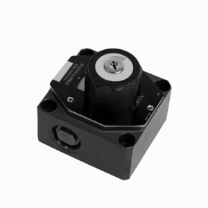
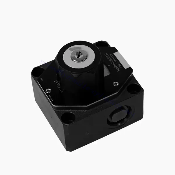
FRM Series Flow Control Hydraulic Valve
Sebagai salah satu produsen, pemasok, dan eksportir silinder hidrolik, Kami menawarkan silinder hidrolik dan banyak produk lainnya.
Silakan hubungi kami untuk informasi lebih lanjut.
Surat:sales@hydraulic-cylinders.net
Produsen pemasok eksportir silinder hidrolik.
FRM Series Flow Control Hydraulic Valve

The FRM series flow control hydraulic valve is a cutting-edge hydraulic component designed to enhance the performance and control of hydraulic systems. With its advanced features and reliable functionality, this valve offers precise flow control and optimal efficiency.
The FRM series flow control hydraulic valve is a reliable and versatile solution for optimizing flow control in hydraulic systems. With its precise flow control capabilities, pressure and temperature stability, and durable construction, this valve offers enhanced performance and efficiency. Following the recommended usage methods and maintenance guidelines, operators can maximize the benefits of the FRM series flow control hydraulic valve, ensuring smooth operation and reliable flow control in their hydraulic applications. Upgrade your hydraulic system with this advanced valve and experience precision, efficiency, and productivity like never before.
FRM Series Flow Control Hydraulic Valve Key Characteristics:
- Flow Control Precision:
- The FRM series valve enables precise control over the flow rate of hydraulic fluids, allowing operators to fine-tune and regulate the speed of actuators.
- With its exceptional accuracy, this valve ensures consistent flow control, resulting in improved system performance and enhanced productivity.
- Versatile Application:
- The FRM series valve is highly versatile and compatible with various hydraulic systems, including industrial machinery, construction equipment, and mobile applications.
- Its adaptability makes it an ideal choice for a wide range of hydraulic setups, providing reliable and efficient flow control.
- Pressure and Temperature Stability:
- This hydraulic valve is designed to maintain consistent flow control even under varying pressure and temperature conditions.
- It ensures stable performance and prevents flow fluctuations, safeguarding the integrity and reliability of the hydraulic system.
- Durable Construction:
- The FRM series valve is constructed with high-quality materials, ensuring durability and long-term reliability in demanding operating environments.
- Its robust design allows it to withstand high pressures, vibrations, and temperature extremes, providing a dependable solution for hydraulic applications.
FRM Series Flow Control Hydraulic Valve Parameter:
NG6
| Flow control valve | |||||||||||
| Max. operating pressure-Port A | bar | 315 | |||||||||
| Pressure differential ΔP for free return flow B to A | See characteristic curves | ||||||||||
| Minimum pressure differential | bar | 6 to 14 | |||||||||
| Pressure stability up to P= 315 bar | % | ±2(Qmax) | |||||||||
| Flow | Qmax | L/min | 0.2 | 0.6 | 1.5 | 3 | 6 | 10 | 16 | 25 | 32 |
| Qmin to 100bar | mL/min | 15 | 15 | 15 | 15 | 25 | 50 | 70 | 100 | 250 | |
| Qmin to 315bar | 25 | 25 | 25 | 25 | 25 | 50 | 70 | 100 | 250 | ||
| Fluid | Mineral oil, Phosphate ester | ||||||||||
| Fluid temperature range | ℃ | – 20 to + 80 | |||||||||
| Viscosity range | mm2/s | 10 to 800 | |||||||||
| Degree of contamination | Maximum permissible degree of fluid contamination: Class 9. NAS 1638 or 20/18/15, ISO4406 | ||||||||||
| Installation position | Optional | ||||||||||
| Circumstances temperature range | ℃ | -20 to +50 | |||||||||
| Weight | 2FRM6A…2FRM6B… | kg | about 1.3 | ||||||||
| 2FRM6SB… | kg | about 1.5 | |||||||||
| Rectifiere | |||||||||||
| Nominal flow | bar | 320 | |||||||||
| Max. operating pressure | bar | to 210 | |||||||||
| Crack pressure | bar | 0.7 | |||||||||
| Weight | kg | about 0.9 | |||||||||
NG5/10/16
| Flow control valve | ||||||||||||||||
| Max. operating pressure-Port A | bar | 315 | ||||||||||||||
| Pressure differential ΔP for free return flow B to A | See characteristic curves | |||||||||||||||
| Minimum pressure differential | bar | 6 to 14 | ||||||||||||||
| Fluid | Mineral oil, Phosphate ester | |||||||||||||||
| Fluid temperature range | ℃ | – 20 to + 80 | ||||||||||||||
| Viscosity range | mm2/s | 10 to 800 | ||||||||||||||
| Degree of contamination | Maximum permissible degree of fluid contamination: Class 9. NAS 1638 or 20/18/15, ISO4406 | |||||||||||||||
| Size | mm | 5 | 10 | 16 | ||||||||||||
| Max. flow-rate | L/min | 0.2 | 0.6 | 1.2 | 3 | 6 | 10 | 15 | 10 | 16 | 25 | 50 | 60 | 100 | 160 | |
| Oil return flow B to A | mL/min | 0.5 | 0.5 | 0.6 | 0.9 | 1.8 | 3.6 | 6.7 | 2 | 2.5 | 3.5 | 6 | 2.8 | 4.3 | 7.3 | |
| flow stable range (%Qmax)(-20-±80℃) | ±5 | ±3 | ±2 | ±2 | ||||||||||||
| ±2 (P=210 bar) | ±2 (P=350 bar) | |||||||||||||||
| Working pressure | bar | 210 | 350 | |||||||||||||
| Min.pressure drawdown | bar | 3-5 | 6-8 | 3-7 | 5-12 | |||||||||||
| Weight | kg | 1.6 | 3.4 | 7.4 | ||||||||||||
| Rectifiere | ||||||||||||||||
| Fluid | Mineral oil, Phosphate ester | |||||||||||||||
| Fluid temperature range | -20 to +80 | |||||||||||||||
| Viscosity range | 10 to 800 | |||||||||||||||
| Degree of contamination | Maximum permissible degree of fluid contamination: Class 9. NAS 1638 or 20/18/15, ISO4406 | |||||||||||||||
| Size | 5 | 10 | 16 | |||||||||||||
| Flow | 15 | 50 | 160 | |||||||||||||
| Working pressure | 210 | 315 | 315 | |||||||||||||
| Crack pressure | 1 | 1.5 | 1.5 | |||||||||||||
| Weight | 0.6 | 3.2 | 9.3 | |||||||||||||
FRM Series Flow Control Hydraulic Valve Advantages:
• Base sub-plate mounting see product catalog
• Pressure compensation displacement restrictor, optional
• Optional one-directional valve
• Knob with scale, optional lockability
Usage Method Of FRM Series Flow Control Hydraulic Valve:
- System Evaluation:
- Begin by assessing the hydraulic system’s requirements, including flow rates, pressure ranges, and desired flow control parameters.
- Determine if the FRM series valve suits the specific application based on its flow control capabilities.
- Valve Selection:
- Select the appropriate variant of the FRM series valve based on the system parameters, desired flow rate, and compatibility with other system components.
- Consider factors such as maximum flow capacity, pressure rating, and operational conditions.
- Installation:
- Follow the manufacturer’s installation instructions carefully, ensuring proper alignment and secure valve connections.
- Pay attention to the flow direction indicators, ensuring the correct positioning of the valve in the hydraulic system.
- Flow Control Adjustment:
- Once installed, adjust the flow control settings of the valve according to the desired flow rate and system requirements.
- Fine-tune the valve to achieve the desired speed and performance of hydraulic actuators, optimizing the overall system operation.
How Hydraulic Valves Work?
Hydraulic valves are crucial in controlling the flow and direction of hydraulic fluid within a hydraulic system. They are essential components that enable the precise operation of various hydraulic machinery and equipment. Here’s a simplified explanation of how hydraulic valves work:
- Basics of Hydraulic Systems:
Hydraulic systems use fluid, typically oil, to transmit power and control the movement of mechanical components. These systems consist of a hydraulic pump that pressurizes the liquid, a series of valves that control the flow and direction of the fluid, and hydraulic actuators (such as cylinders or motors) that convert the fluid energy into mechanical force or motion. - Valve Types:
There are various hydraulic valves, including directional control valves, pressure control valves, flow control valves, and check valves. Each valve type serves a specific purpose in regulating fluid flow, pressure, or direction. - Directional Control Valves:
Directional control valves determine the path through which the hydraulic fluid flows. They have multiple positions (such as open, closed, or partially open) and multiple ports to direct the fluid to different sections of the hydraulic system. - Valve Components:
Hydraulic valves typically consist of a valve body, which contains internal passages and channels, and a movable valve element or spool that slides within the valve body. The spool has different lands or ports that align with the internal passages to control fluid flow. - Spool Movement:
The position of the spool within the valve body determines the flow path and, consequently, the direction of fluid flow. The spool can be actuated by various means, such as mechanical linkages, solenoids, or pilot pressure. - Pressure Control Valves:
Pressure control valves regulate the pressure of the hydraulic fluid within the system. They can maintain a specific pressure level by allowing excess fluid to return to the reservoir or blocking flow until a desired pressure is reached. - Flow Control Valves:
Flow control valves manage the rate of fluid flow within the hydraulic system. They can be used to control the speed of hydraulic actuators or to limit the flow rate to specific sections of the system. - Check Valves:
Check valves, or one-way valves, allow fluid flow in one direction and prevent backflow. They ensure that the fluid moves in the desired direction and avoid any undesired pressure drops or loss of hydraulic force. - Valve Actuation:
Hydraulic valves can be manually operated, mechanically actuated, or controlled electronically. Levers or knobs directly handle manual valves, while mechanical and electronic actuators enable automated control of valve positions based on system requirements. - System Control:
By combining different types of hydraulic valves and controlling their positions or actuation, the hydraulic system’s overall function can be precisely regulated. This enables operators to control the movement, speed, force, and direction of hydraulic actuators, allowing for precise and efficient operation of hydraulic machinery.
Kemampuan & Kapasitas Pabrik:
(1) Perakitan
Kami memiliki platform perakitan penelitian dan pengembangan independen kelas satu. Bengkel produksi silinder hidrolik memiliki empat jalur perakitan silinder pengangkat semi-otomatis dan satu jalur perakitan silinder kemiringan otomatis, dengan kapasitas produksi tahunan yang dirancang sebesar 1 juta keping. Bengkel silinder khusus dilengkapi dengan berbagai spesifikasi sistem perakitan pembersihan semi-otomatis dengan kapasitas produksi tahunan yang dirancang sebesar 200.000 dan dilengkapi dengan peralatan permesinan CNC yang terkenal, pusat permesinan, peralatan khusus pemrosesan silinder presisi tinggi, mesin las robot, mesin pembersih otomatis, mesin perakitan silinder otomatis, dan jalur produksi pengecatan otomatis. Peralatan penting yang ada lebih dari 300 set (set). Alokasi optimal dan penggunaan sumber daya peralatan yang efisien memastikan persyaratan akurasi produk dan memenuhi kebutuhan produk berkualitas tinggi.


(2) Pemesinan
Bengkel permesinan dilengkapi dengan pusat pembubutan rel miring yang disesuaikan, pusat permesinan, mesin pengasah berkecepatan tinggi, robot pengelasan, dan peralatan terkait lainnya, yang dapat menangani pemrosesan tabung silinder dengan diameter bagian dalam maksimum 400mm dan panjang maksimum 6 meter.

(3) Pengelasan

(4) Pengecatan & pelapisan
Dengan jalur pelapisan cat berbasis air otomatis silinder kecil dan menengah, untuk mencapai bongkar muat robot otomatis dan penyemprotan otomatis, kapasitas desain 4000 buah per shift;
Kami juga memiliki lini produksi cat semi-otomatis untuk silinder besar yang ditenagai oleh rantai daya, dengan kapasitas desain 60 kasus per shift.


(5) Pengujian
Kami memiliki fasilitas inspeksi kelas satu dan test bed untuk memastikan bahwa kinerja silinder memenuhi persyaratan.

We are one of the best hydraulic cylinder manufacturers. We can offer comprehensive hydraulic cylinders. We also provide corresponding gearbox pertanian. Kami telah mengekspor produk kami ke klien di seluruh dunia dan mendapatkan reputasi yang baik karena kualitas produk dan layanan purna jual kami yang unggul. Kami menyambut pelanggan di dalam dan luar negeri untuk menghubungi kami untuk menegosiasikan bisnis, bertukar informasi, dan bekerja sama dengan kami!
Ikuti Tur Pabrik VR Kami:
Ikuti tur ke pabrik VR kami dengan yang berikut ini
Aplikasi Silinder Hidraulik:


