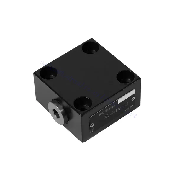
Valvola idraulica di controllo direzionale serie L-LFA
In qualità di uno dei produttori, fornitori ed esportatori di prodotti meccanici, offriamo cilindri idraulici e molti altri prodotti.
Per maggiori dettagli, contattateci.
Posta:sales@hydraulic-cylinders.net
Produttore fornitore esportatore di cilindri idraulici.
Valvola idraulica di controllo direzionale serie L-LFA
The L-LFA series directional control hydraulic valve is a cutting-edge component designed to deliver precise control and optimal performance in hydraulic systems. With its advanced features and robust construction, this valve provides reliable and efficient directional control for various applications.
The L-LFA series directional control hydraulic valve is a game-changer for hydraulic systems, offering precise directional control, versatility, and durability. By following the recommended usage methods and maintenance guidelines, you can harness the full potential of the L-LFA series valve and experience enhanced control, efficiency, and productivity in your hydraulic applications. Upgrade your hydraulic system today and unlock the advantages of precision and efficiency with the L-LFA series directional control hydraulic valve.
L-LFA Series Directional Control Hydraulic Valve Key Characteristics:
- Accurate Directional Control:
- The L-LFA series valve offers exceptional directional control, allowing precise and efficient management of fluid flow in hydraulic systems.
- This characteristic enables operators to direct hydraulic fluid to specific actuators or hydraulic components, facilitating smooth and controlled movement.
- Versatile Configuration Options:
- This valve is available in various configurations, including 2-way, 3-way, and 4-way options, ensuring compatibility with diverse hydraulic system requirements.
- The 2-way configuration facilitates simple on/off control, while the 3-way and 4-way configurations enable more complex functions such as cylinder extension, retraction, and bi-directional control.
- High-Performance Construction:
- The L-LFA series valve is engineered with high-quality materials and precision manufacturing techniques to ensure durability and longevity.
- Its robust construction allows it to withstand high pressures, temperature variations, and harsh operating conditions, ensuring reliable performance even in demanding environments.
- Tempo di risposta rapido:
- This valve boasts an impressive response time, enabling rapid and efficient fluid flow control within the hydraulic system.
- The quick response time facilitates precise and immediate adjustments, resulting in enhanced system performance and reduced energy consumption.
L-LFA Series Directional Control Hydraulic Valve Parameter:
| Pressione massima di esercizio | Without directional valve | sbarra | 420 | |||||
| – Oil port A、B、X、Z1、Z2 | sbarra | 315; 350; 420(Depends on top-mounted directional valve) | ||||||
| – Oil port Y | sbarra | Equivalent to the return pressure of a top-mounted directional valve | ||||||
| Fluido | Olio minerale adatto per guarnizioni NBR e FKM | |||||||
| Estere fosfatico per guarnizione FKM | ||||||||
| Intervallo di temperatura del fluido | °C | -30 a +80 (guarnizione NBR) | ||||||
| -20 a +80 (guarnizione FKM) | ||||||||
| intervallo di viscosità | mm2/S | da 2,8 a 380 | ||||||
| Grado di contaminazione | Maximum permissible degree of fluid contamination: Class 9. NAS 1638 or 20/18/15 , ISO4406 | |||||||
L-LFA Series Directional Control Hydraulic Valve Advantages:
• Basic type D with remote control
• With stroke limiter H
• Built-in shuttle valve G
• Built-in directional seat valve R, RF
• Can be equipped with directional valve WE
Usage Method Of L-LFA Series Directional Control Hydraulic Valve:
- Valutazione del sistema:
- Evaluate your hydraulic system and identify the specific directional control requirements.
- Determine whether the L-LFA series valve suits your system based on flow rates, pressure ratings, and compatibility with your application.
- Selezione della valvola:
- Select the appropriate variant of the L-LFA series valve based on your system parameters and directional control needs.
- Consider factors such as valve type (2-way, 3-way, or 4-way), flow capacity, pressure rating, and compatibility with your specific application.
- Installazione:
- Seguire attentamente le istruzioni di installazione del produttore per garantire un allineamento corretto e un montaggio sicuro della valvola.
- Use compatible hydraulic fittings, adapters, and seals to establish leak-free connections. Tighten the connections adequately, avoiding overtightening that could damage the valve or fittings.
- Integrazione di sistema:
- Connect the hydraulic lines to the appropriate ports of the L-LFA series valve, ensuring the correct flow direction.
- Verify that the valve is installed in the correct orientation, as indicated by the directional arrows on the valve body.
- Funzionamento e controllo:
- Familiarize yourself with the control mechanisms of the L-LFA Series Valve, such as levers, knobs, or solenoids.
- Ensure that the valve is actuated correctly and that the desired hydraulic flow is achieved based on the system requirements.
Come installare una valvola di sicurezza idraulica?
L'installazione di una valvola di sicurezza idraulica è un passaggio fondamentale per garantire la sicurezza e il corretto funzionamento di un impianto idraulico. Ecco una guida passo passo su come installare una valvola di sicurezza idraulica:
- Identificare la valvola: Determina il tipo e il modello specifico della valvola di sicurezza idraulica con cui lavori. Assicurati che sia adatta alla tua applicazione e compatibile con i requisiti del tuo sistema idraulico.
- Raccogli gli strumenti e i materiali necessari: Raccogliere gli strumenti e i materiali necessari, inclusi raccordi idraulici appropriati, adattatori, chiavi inglesi, nastro in Teflon (sigillante per filettature) e un manometro, se necessario. Consultare le istruzioni del produttore per eventuali strumenti o componenti specifici richiesti.
- Preparare il sistema idraulico: Arrestare l'impianto idraulico e scaricare la pressione attivando la valvola di sicurezza o retraendo i cilindri idraulici. Questo passaggio è fondamentale per la sicurezza e impedisce movimenti accidentali o fuoriuscite di fluido idraulico.
- Identificare il punto di rilascio della pressione: Determinare la posizione ottimale per installare la valvola di sicurezza idraulica nel sistema idraulico. Dovrebbe essere posizionata a valle della pompa, prima di eventuali componenti sensibili, per proteggerli da pressioni eccessive. Consultare lo schema del sistema idraulico o, se necessario, consultare un professionista.
- Montare la valvola: Montare saldamente la valvola di sicurezza idraulica nella posizione prescelta utilizzando staffe o morsetti appropriati. Assicurarsi che la valvola sia posizionata correttamente, allineando le porte di ingresso e di uscita con la direzione del flusso. Seguire le istruzioni del produttore per i requisiti di montaggio specifici.
- Collegare le porte di ingresso e di uscita: Collegare tubi flessibili o tubazioni idrauliche alle porte di ingresso e di uscita della valvola di sicurezza. Utilizzare raccordi idraulici e adattatori idonei per creare un collegamento a tenuta stagna. Applicare nastro in Teflon o sigillante per filettature alle filettature maschio dei raccordi per garantire un collegamento sicuro e a tenuta. Serrare i collegamenti utilizzando chiavi inglesi per evitare perdite, ma fare attenzione a non serrare eccessivamente.
- Impostare l'impostazione di scarico della pressione: La maggior parte delle valvole di sicurezza idrauliche è dotata di un'impostazione di sicurezza regolabile. Regolare la valvola di sicurezza al punto di sicurezza desiderato seguendo le istruzioni del produttore. Alcune valvole potrebbero richiedere un manometro per impostare con precisione la pressione di sicurezza. Installare temporaneamente il manometro, se necessario, e regolare la valvola di sicurezza fino a raggiungere la pressione desiderata.
- Testare il sistema: Una volta installata la valvola di sicurezza idraulica, ripristinare lentamente la pressione del sistema idraulico. Monitorare il manometro o osservare il comportamento del sistema per assicurarsi che la valvola di sicurezza funzioni correttamente. La valvola di sicurezza dovrebbe aprirsi e deviare la pressione in eccesso quando raggiunge il punto di regolazione, evitando danni al sistema.
- Monitorare e mantenere: Ispezionare regolarmente la valvola di sicurezza idraulica per individuare eventuali perdite, danni o prestazioni ridotte. Pulire la valvola e l'area circostante per rimuovere sporco e detriti che potrebbero comprometterne il funzionamento. Seguire il programma di manutenzione e le linee guida consigliate dal produttore per garantire prestazioni ottimali e longevità.
Capacità e capacità della fabbrica:
(1) Montaggio
Disponiamo di una piattaforma di assemblaggio indipendente di ricerca e sviluppo di prima classe. L'officina di produzione di cilindri idraulici dispone di quattro linee di assemblaggio semiautomatiche per cilindri di sollevamento e una linea di assemblaggio automatica per cilindri di inclinazione, con una capacità produttiva annua progettata di 1 milione di pezzi. L'officina per cilindri speciali è dotata di un sistema di assemblaggio semiautomatico per la pulizia con diverse specifiche, con una capacità produttiva annua progettata di 200.000 pezzi e dotata di rinomate macchine per lavorazioni meccaniche CNC, un centro di lavoro, attrezzature speciali per la lavorazione di cilindri ad alta precisione, una macchina per saldatura robotizzata, una macchina per la pulizia automatica, una macchina per l'assemblaggio automatico dei cilindri e una linea di produzione per la verniciatura automatica. Sono disponibili oltre 300 set di attrezzature critiche. L'allocazione ottimale e l'uso efficiente delle risorse delle attrezzature garantiscono i requisiti di precisione dei prodotti e ne soddisfano le elevate esigenze di qualità.


(2) Lavorazione
L'officina di lavorazione è dotata di un centro di tornitura su rotaia inclinata personalizzato, di un centro di lavorazione, di una levigatrice ad alta velocità, di un robot di saldatura e di altre attrezzature correlate, in grado di gestire la lavorazione di tubi cilindrici con un diametro interno massimo di 400 mm e una lunghezza massima di 6 metri.

(3) Saldatura

(4) Verniciatura e rivestimento
Con linee automatiche di verniciatura a base d'acqua a cilindro di piccole e medie dimensioni, per realizzare il carico e lo scarico automatico con robot e la spruzzatura automatica, la capacità di progettazione è di 4000 pezzi per turno;
Disponiamo anche di una linea di produzione semiautomatica di vernici per cilindri di grandi dimensioni alimentata da una catena di potenza, con una capacità di progettazione di 60 casse per turno.


(5) Test
Disponiamo di strutture di ispezione e banchi di prova di prim'ordine per garantire che le prestazioni del cilindro siano conformi ai requisiti.

Siamo uno dei migliori produttori di cilindri idraulici. Offriamo una gamma completa di cilindri idraulici. Forniamo anche i relativi componenti. riduttori agricoliAbbiamo esportato i nostri prodotti a clienti in tutto il mondo e ci siamo guadagnati un'ottima reputazione grazie alla qualità superiore dei nostri prodotti e al servizio post-vendita. Invitiamo i clienti nazionali e internazionali a contattarci per negoziare affari, scambiare informazioni e collaborare con noi!
Cilindro idraulico Applicazione:
