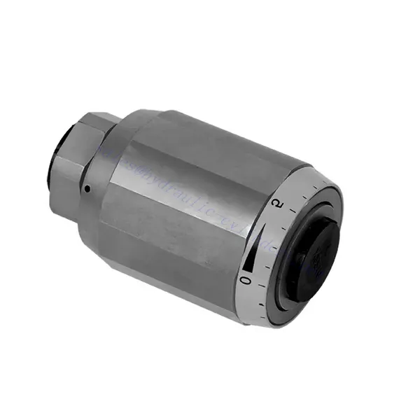
Valvola idraulica di controllo dell'acceleratore e dell'acceleratore serie MG/MK
In qualità di uno dei produttori, fornitori ed esportatori di prodotti meccanici, offriamo cilindri idraulici e molti altri prodotti.
Per maggiori dettagli, contattateci.
Posta:sales@hydraulic-cylinders.net
Produttore fornitore esportatore di cilindri idraulici.
Valvola idraulica di controllo dell'acceleratore e dell'acceleratore serie MG/MK
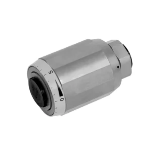
The MG/MK series throttle and throttle check hydraulic valve is a versatile and high-performance hydraulic component designed to optimize control and efficiency in hydraulic systems. With its unique throttle and throttle check functionality, this valve offers precise flow control and ensures the smooth operation of hydraulic actuators.
The MG/MK series throttle and throttle check hydraulic valve is a versatile and reliable solution for precise flow control and enhanced system efficiency. With its throttle functionality, throttle check feature, and customizable flow control options, this valve delivers exceptional performance in various hydraulic applications. Following the recommended usage methods and maintenance guidelines, operators can ensure the longevity, reliability, and optimal functionality of the MG/MK series throttle and check hydraulic valve. Upgrade your hydraulic system with this advanced valve and experience enhanced control, efficiency, and productivity.
MG/MK Series Throttle And Throttle Check Hydraulic Valve Key Characteristics:
- Throttle Functionality:
- The MG/MK series valve features a throttle function that regulates the flow rate of hydraulic fluid.
- It allows for precise control of the fluid flow, enabling fine-tuning of actuator speed and responsiveness.
- Throttle Check Function:
- In addition to throttle control, this valve incorporates a throttle check function.
- The throttle check feature enables the valve to act as a check valve, preventing reverse flow and maintaining system stability.
- Flow Control Versatility:
- The MG/MK Series Valve offers a wide range of flow control options, allowing customization to suit specific application requirements.
- It can be configured for varying flow rates, pressure differentials, and actuator sizes, ensuring compatibility with diverse hydraulic systems.
- Efficienza del sistema migliorata:
- By providing precise flow control, the valve minimizes energy loss and optimizes overall system efficiency.
- It allows operators to match the hydraulic flow to the specific load requirements, reducing unnecessary power consumption.
- Prestazioni affidabili:
- The MG/MK Series Valve is built to withstand demanding operating conditions and deliver consistent performance.
- Its robust construction and high-quality materials ensure durability and reliability in various applications.
MG/MK Series Throttle And Throttle Check Hydraulic Valve Parameter:
| Misurare | 6 | 8 | 10 | 15 | 20 | 25 | 30 | |
| Peso | kg | 0.3 | 0.4 | 0.7 | 1.3 | 2.2 | 3.6 | 4.5 |
| Pressione massima di esercizio | sbarra | 315bar | ||||||
| Cracking pressure for type MK | sbarra | 0.5 | ||||||
| Portata massima | litri/min | 400 | ||||||
| intervallo di viscosità | mm2/S | da 10 a 800 | ||||||
| Intervallo di temperatura del fluido | °C | -30℃ to +80℃ | ||||||
| Fluido | Olio minerale; estere fosfatico | |||||||
| Grado di contaminazione | Grado massimo consentito di contaminazione del fluido: Classe 9. NAS 1638 o 20/18/15, ISO4406 | |||||||
MG/MK Series Throttle And Throttle Check Hydraulic Valve Advantages:
• Used in direct tubing installation
• Related to pressure and viscosity
Usage Method Of MG/MK Series Throttle And Throttle Check Hydraulic Valve:
- Valutazione del sistema:
- Assess the hydraulic system’s requirements, including flow rates, pressure differentials, and actuator specifications.
- Identify the need for throttle and throttle check functionality in the system.
- Selezione della valvola:
- Select the appropriate variant of the MG/MK series valve based on system parameters and desired flow control characteristics.
- Consider factors such as maximum flow rate, pressure rating, and compatibility with other system components.
- Installazione:
- Follow the manufacturer’s installation instructions and ensure proper alignment and connection of the valve.
- Pay attention to flow direction arrows and ensure secure fittings and seals.
- Flow Adjustment:
- Adjust the throttle setting on the valve to achieve the desired flow rate.
- Fine-tune the throttle control to optimize actuator performance and system efficiency.
How Hydraulic Control Valve Works?
A hydraulic control valve is a critical component in hydraulic systems that regulates the flow and pressure of hydraulic fluid. It serves as a control mechanism for directing fluid to different hydraulic actuators and controlling the speed and direction of their movement. The operation of a hydraulic control valve can be described as follows:
- Struttura della valvola:
- A hydraulic control valve comprises a valve body that houses various internal components, such as spools, poppets, or discs.
- The valve body contains ports, passages, and chambers that facilitate the flow of hydraulic fluid.
- Posizioni delle valvole:
- Hydraulic control valves typically have multiple positions, including open, closed, and partially open.
- In posizione chiusa, la valvola blocca completamente il flusso del fluido.
- In the open position, the valve allows fluid to flow freely through specific ports.
- Nella posizione parzialmente aperta, la valvola limita o controlla la portata del fluido.
- Funzionamento della valvola a cassetto:
- Spool valves are commonly used in hydraulic control systems. They consist of a cylindrical spool with lands or channels.
- The spool is positioned within the valve body and can be moved longitudinally.
- By shifting the spool, different lands align with specific ports, enabling or blocking fluid flow to different actuators.
- The movement of the spool is typically achieved using mechanical linkages, solenoids, or hydraulic pressure acting on the spool.
- Funzionamento della valvola a fungo:
- Poppet valves are another type of hydraulic control valve. They use a movable poppet or disc to control fluid flow.
- Quando il fungo è in posizione chiusa, poggia contro una sede, bloccando il flusso del fluido.
- Per aprire la valvola, il otturatore viene allontanato dalla sede, consentendo al fluido di fluire attraverso il passaggio.
- The movement of the poppet can be achieved through mechanical linkages or hydraulic pressure.
- Meccanismi di controllo:
- Hydraulic control valves can be operated manually, mechanically, or through electrical means.
- Manual control involves the use of levers, knobs, or handles to position the valve element.
- Il controllo meccanico utilizza collegamenti meccanici o attuatori per muovere l'elemento valvola.
- Il controllo elettrico impiega solenoidi o altri dispositivi controllati elettricamente per spostare l'elemento valvola.
- Controllo attuatore:
- Hydraulic control valves direct fluid to various hydraulic actuators, such as cylinders or motors.
- By controlling the valve positions, the hydraulic system can regulate the speed, direction, and force of the actuators.
- For example, adjusting the valve position can control the extension or retraction of a hydraulic cylinder.
- Stabilità e sicurezza del sistema:
- Hydraulic control valves play a crucial role in maintaining system stability and safety.
- Pressure relief valves are often incorporated into hydraulic control systems to protect against overpressure.
- These relief valves divert excess fluid to a low-pressure outlet, preventing damage to the system.
Capacità e capacità della fabbrica:
(1) Montaggio
Disponiamo di una piattaforma di assemblaggio indipendente di ricerca e sviluppo di prima classe. L'officina di produzione di cilindri idraulici dispone di quattro linee di assemblaggio semiautomatiche per cilindri di sollevamento e una linea di assemblaggio automatica per cilindri di inclinazione, con una capacità produttiva annua progettata di 1 milione di pezzi. L'officina per cilindri speciali è dotata di un sistema di assemblaggio semiautomatico per la pulizia con diverse specifiche, con una capacità produttiva annua progettata di 200.000 pezzi e dotata di rinomate macchine per lavorazioni meccaniche CNC, un centro di lavoro, attrezzature speciali per la lavorazione di cilindri ad alta precisione, una macchina per saldatura robotizzata, una macchina per la pulizia automatica, una macchina per l'assemblaggio automatico dei cilindri e una linea di produzione per la verniciatura automatica. Sono disponibili oltre 300 set di attrezzature critiche. L'allocazione ottimale e l'uso efficiente delle risorse delle attrezzature garantiscono i requisiti di precisione dei prodotti e ne soddisfano le elevate esigenze di qualità.


(2) Lavorazione
L'officina di lavorazione è dotata di un centro di tornitura su rotaia inclinata personalizzato, di un centro di lavorazione, di una levigatrice ad alta velocità, di un robot di saldatura e di altre attrezzature correlate, in grado di gestire la lavorazione di tubi cilindrici con un diametro interno massimo di 400 mm e una lunghezza massima di 6 metri.

(3) Saldatura

(4) Verniciatura e rivestimento
Con linee automatiche di verniciatura a base d'acqua a cilindro di piccole e medie dimensioni, per realizzare il carico e lo scarico automatico con robot e la spruzzatura automatica, la capacità di progettazione è di 4000 pezzi per turno;
Disponiamo anche di una linea di produzione semiautomatica di vernici per cilindri di grandi dimensioni alimentata da una catena di potenza, con una capacità di progettazione di 60 casse per turno.


(5) Test
Disponiamo di strutture di ispezione e banchi di prova di prim'ordine per garantire che le prestazioni del cilindro siano conformi ai requisiti.

Siamo uno dei migliori produttori di cilindri idraulici. Offriamo una gamma completa di cilindri idraulici. Forniamo anche i relativi componenti. riduttori agricoliAbbiamo esportato i nostri prodotti a clienti in tutto il mondo e ci siamo guadagnati un'ottima reputazione grazie alla qualità superiore dei nostri prodotti e al servizio post-vendita. Invitiamo i clienti nazionali e internazionali a contattarci per negoziare affari, scambiare informazioni e collaborare con noi!
Cilindro idraulico Applicazione:
