4WRA(E) სერიის პირდაპირი ოპერირების პროპორციული მიმართულების ჰიდრავლიკური სარქველი
4WRA(E) სერიის პირდაპირი ოპერირების პროპორციული მიმართულების ჰიდრავლიკური სარქველი
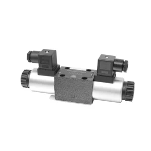
4WRA(E) სერიის პირდაპირი მართვის პროპორციული მიმართულების ჰიდრავლიკური სარქველი წარმოადგენს ულტრათანამედროვე ჰიდრავლიკურ კომპონენტს, რომელიც შექმნილია ჰიდრავლიკურ სისტემებში ზუსტი კონტროლისა და ეფექტური მუშაობის უზრუნველსაყოფად. პირდაპირი მართვის პროპორციული მიმართულების მართვის ტექნოლოგიით, ეს სარქველი გთავაზობთ ნაკადის ზუსტ კონტროლს, მიმართულების შეუფერხებელ ცვლილებას და ოპტიმიზებულ მუშაობას.
4WRA(E) სერიის პირდაპირი მართვის პროპორციული მიმართულების ჰიდრავლიკური სარქველი ჰიდრავლიკურ სისტემებს აწვდის ზუსტი ნაკადის კონტროლს, მრავალმხრივ მიმართულების ცვლილებებს და ოპტიმალურ ენერგოეფექტურობას. მისი პირდაპირი მართვის პროპორციული მართვის ტექნოლოგია უზრუნველყოფს ზუსტ და რეაგირებად მუშაობას, ხოლო მაღალი ნაკადის ტევადობა და ენერგოეფექტური დიზაინი ხელს უწყობს სისტემის მუშაობის გაუმჯობესებას. რეკომენდებული გამოყენების მეთოდებისა და მოვლა-პატრონობის ინსტრუქციების დაცვით, თქვენ შეგიძლიათ მაქსიმალურად გაზარდოთ 4WRA(E) სერიის სარქვლის სარგებელი და ხანგრძლივობა, რაც თქვენს ჰიდრავლიკურ სისტემას სიზუსტისა და ეფექტურობის ახალ დონეზე აიყვანს. განაახლეთ თქვენი ჰიდრავლიკური სისტემა დღესვე და გამოსცადეთ 4WRA(E) სერიის პირდაპირი მართვის პროპორციული მიმართულების ჰიდრავლიკური სარქვლის სიმძლავრე.
4WRA(E) სერიის პირდაპირი ოპერირების პროპორციული მიმართულების ჰიდრავლიკური სარქვლის ძირითადი მახასიათებლები:
- პირდაპირი პროპორციული კონტროლი:
- 4WRA(E) სერიის სარქველი იყენებს პირდაპირი მოქმედების პროპორციულ კონტროლს, რაც საშუალებას იძლევა ზუსტი და მყისიერი რეაგირება მოხდეს მართვის სიგნალებზე.
- ეს მახასიათებელი უზრუნველყოფს ნაკადის ზუსტ კონტროლს და სხვადასხვა ჰიდრავლიკურ ფუნქციებს შორის შეუფერხებელ გადასვლას.
- მაღალი ნაკადის ტევადობა:
- თავისი მყარი დიზაინის წყალობით, სარქველი უზრუნველყოფს მაღალი ნაკადის გამტარუნარიანობას, რაც მას შესაფერისს ხდის მნიშვნელოვანი ჰიდრავლიკური სიმძლავრის მოთხოვნით დამუშავებისთვის.
- ეს საშუალებას იძლევა ეფექტურად დამუშავდეს დიდი მოცულობის სითხეები, რაც ხელს უწყობს სისტემის მუშაობის გაუმჯობესებას.
- მრავალმხრივი მიმართულების კონტროლი:
- 4WRA(E) სერიის სარქველი უზრუნველყოფს მრავალმხრივ მიმართულების კონტროლს, რაც უზრუნველყოფს ჰიდრავლიკური სითხის მიმართულების გლუვ და ზუსტ ცვლილებას.
- ის საშუალებას იძლევა ჰიდრავლიკური კომპონენტების, როგორიცაა ცილინდრები, ძრავები და აქტივატორები, შეუფერხებლად გააქტიურდეს სხვადასხვა მიმართულებით.
- ენერგოეფექტურობა:
- ენერგოეფექტურობის გათვალისწინებით შექმნილი ეს სარქველი მინიმუმამდე ამცირებს წნევის ვარდნას და ოპტიმიზაციას უკეთებს ნაკადის კონტროლს, რაც იწვევს ენერგიის მოხმარების შემცირებას.
- ჰიდრავლიკური ენერგიის ეფექტურად მართვის გზით, ის ხელს უწყობს სისტემის მუშაობის მაქსიმიზაციას და ამავდროულად ოპერაციული ხარჯების შემცირებას.
4WRA (E) სერიის პირდაპირი ოპერირებადი პროპორციული მიმართულების ჰიდრავლიკური სარქვლის პარამეტრი:
| ჰიდრავლიკური | ||||||||
| ინსტალაციის პოზიცია | სურვილისამებრ, სასურველია ჰორიზონტალური | |||||||
| ზომა | 6 | 10 | ||||||
| წონა | 4WRA…L2X | კგ | 2 | 6.6 | ||||
| 4WRAE…L2X | 2.2 | 6.8 | ||||||
| ნომინალური ნაკადის qnom, როდესაც Δp = 10 ბარი | ლ/წთ | 7, 15, 26 | 30, 60 | |||||
| ჰისტერეზისი | % | ≤5 | ||||||
| განმეორებადობა | % | ≤1 | ||||||
| რეაქციის მგრძნობელობა | % | ≤0.5 | ||||||
| მაქსიმალური სამუშაო წნევა | პორტის ABP | ბარი | 315 | |||||
| პორტი T | ბარი | 210 | ||||||
| სითხე | მინერალური ზეთი, შესაფერისი NBR და FKM დალუქვისთვის | |||||||
| ფოსფატის ეთერი FKM დალუქვისთვის | ||||||||
| სითხის ტემპერატურის დიაპაზონი | 4WRA…L2X | ℃ | -20℃-დან 70℃-მდე (-4°F-დან 158°F-მდე) | |||||
| 4WRAE…L2X | ℃ | -20℃-დან 50℃-მდე (-4° F-დან 122° F-მდე) | ||||||
| სიბლანტის დიაპაზონი | მმ²/წმ | 20-დან 380-მდე (სასურველია 30-დან 46-მდე) | ||||||
| დაბინძურების ხარისხი | NAS1638 კლასი 9 ან ISO 4406 კლასი 20/18/15 | |||||||
| ელექტრო მონაცემები | ||||||||
| 1) სოლენოიდი | ||||||||
| ძაბვის ტიპი | ვაშინგტონი | |||||||
| ბრძანების მნიშვნელობის სიგნალი | ±10 ვ ან 4~20 მA | |||||||
| მაქსიმალური დენი თითო სოლენოიდზე | ა | 2.5 | 1.5 | 0.8 | ||||
| ხვეულის წინააღმდეგობა | ცივი ღირებულება | ომეგა | 2 | 4.8 | 19.5 | |||
| მაქსიმალური სითბოს მნიშვნელობა | 3 | 7.2 | 28.8 | |||||
| მოვალეობა | % | ED100% | ||||||
| ხვეულის ტემპერატურა | ℃ | 150 | ||||||
| სარქვლის დაცვა EN 60529 სტანდარტის შესაბამისად | IP 65 | |||||||
| 2) მართვის ელექტრონიკა | ||||||||
| ამპილფიერი | 4WRA…L2X | VT-VSPA2-L2X | ||||||
| 4WRAE…L2X | ინტეგრირებულია სარქველში (OBE) | |||||||
| ოპერაციული ძაბვა | ნომინალური ძაბვა | VDC | 24 | |||||
| ქვედა ზღვრული მნიშვნელობა | ვ | 21/22 (4WRA), 19 (4WRAE) | ||||||
| ზედა ზღვრული მნიშვნელობა | ვ | 35 | ||||||
| გამაძლიერებლის მიმდინარე მოხმარება | იმაქსი | ა | <1.8 | |||||
| იმაქსი | ა | 3 | ||||||
4WRA(E) სერიის პირდაპირი ოპერირებადი პროპორციული მიმართულების ჰიდრავლიკური სარქვლის უპირატესობები:
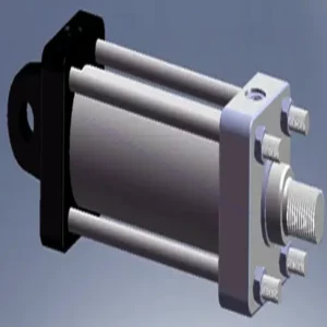
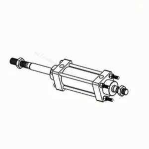
• პირდაპირი მოქმედების პროპორციული მიმართულების სარქველი, რომელიც გამოიყენება სითხის ნაკადისა და მიმართულების გასაკონტროლებლად
• პანელის ტიპის მონტაჟი
• პროპორციული სოლენოიდი ხრახნიანი შეერთების მეშვეობით ააქტიურებს სარქვლის ბირთვს და კოჭა შეიძლება ცალკე მოიხსნას.
• კოჭის ზამბარის გასწორება
• ჩაშენებული გამაძლიერებლით სურვილისამებრ, 4WRAE…L2X ტიპის შეყვანა შეიძლება იყოს A1 ან F1
• გარე გამაძლიერებლის დამხმარე კვება
4WRA (E) სერიის პირდაპირი მოქმედების პროპორციული მიმართულების ჰიდრავლიკური სარქვლის გამოყენების მეთოდი:
- სისტემის შეფასება:
- შეაფასეთ თქვენი ჰიდრავლიკური სისტემა და დაადგინეთ ნაკადის კონტროლისა და მიმართულების სპეციფიკური მოთხოვნები.
- განსაზღვრეთ, შესაფერისია თუ არა 4WRA(E) სერიის სარქველი მისი ნაკადის სიმძლავრის, წნევის ნომინალური მაჩვენებლისა და თქვენს სისტემასთან თავსებადობის მიხედვით.
- სარქვლის შერჩევა:
- თქვენი სისტემის პარამეტრების, ნაკადის მოთხოვნებისა და მიმართულების კონტროლის საჭიროებების საფუძველზე, აირჩიეთ 4WRA(E) სერიის სარქვლის შესაბამისი ვარიანტი.
- გაითვალისწინეთ ისეთი ფაქტორები, როგორიცაა მაქსიმალური ნაკადის სიჩქარე, წნევის რეიტინგი, რეაგირების დრო და ექსპლუატაციის პირობები.
- ინსტალაცია:
- ყურადღებით მიჰყევით მწარმოებლის ინსტალაციის ინსტრუქციებს, უზრუნველყავით სარქვლის სწორი გასწორება და უსაფრთხოდ დამაგრება.
- შეაერთეთ სარქველი ჰიდრავლიკურ სისტემასთან, უზრუნველყავით გაჟონვისგან თავისუფალი კავშირები და ნაკადის მიმართულების სწორი გასწორება.
- საკონტროლო სიგნალის კავშირი:
- სარქვლის მართვის სიგნალის სადენები შეაერთეთ შესაბამის მართვის მოწყობილობასთან, როგორიცაა პროპორციული გამაძლიერებელი ან ელექტრონული მართვის ბლოკი.
- ზუსტი და სწრაფი კონტროლის უზრუნველსაყოფად, უზრუნველყავით სარქველსა და მართვის მოწყობილობას შორის სათანადო გაყვანილობა და თავსებადობა.
როგორ დავარეგულიროთ სარქვლის სამაგრი ჰიდრავლიკურ ამწეებზე?
ჰიდრავლიკური ამწეების სარქვლის რგოლის რეგულირება ძრავის სათანადო მუშაობის უზრუნველსაყოფად და ისეთი პრობლემების თავიდან ასაცილებლად, როგორიცაა ხმაურიანი სარქველები ან სიმძლავრის შემცირება. აქ მოცემულია ეტაპობრივი ინსტრუქცია, თუ როგორ უნდა დაარეგულიროთ სარქვლის რგოლი ჰიდრავლიკურ ამწეებზე:
- მომზადება:
- რეგულირების პროცესის დაწყებამდე დარწმუნდით, რომ ძრავა გამორთულია და გაგრილებულია.
- გაეცანით ძრავის ჩართვის თანმიმდევრობას და მწარმოებლის მიერ თქვენი ძრავის მოდელისთვის მოწოდებულ სარქვლის ლენტის სპეციფიკაციებს.
- სწორი ცილინდრის იდენტიფიცირება:
- ძრავის ჩართვის პოზიციის დასადგენად, ძრავის ჩართვის თანმიმდევრობის დიაგრამის გამოყენებით განსაზღვრეთ.
- დაადგინეთ ცილინდრი, რომელიც შეესაბამება იმ კონკრეტულ სარქველს, რომლის რეგულირებაც გსურთ.
- ცილინდრის განთავსება:
- ძრავის ამწე ლილვი ხელით მოატრიალეთ ბუდის გასაღების ან ძრავში ჩაშენებული მბრუნავი მექანიზმის გამოყენებით.
- ცილინდრი, რომლის რეგულირებაც გსურთ, შეკუმშვის ინსულტის ზედა მკვდარ წერტილში (TDC) მოათავსეთ. ამის გაკეთება შეგიძლიათ მუხლა ლილვის ბორბალზე დროის აღმნიშვნელი ნიშნების გასწორებით ან დგუშის გაჩერების ხელსაწყოს გამოყენებით.
- მოხსენით საქანელა მკლავი:
- იპოვეთ საქანელა მკლავი კონკრეტულ სარქველზე, რომლის რეგულირებაც გსურთ.
- მოხსენით საქანელა მკლავის ჭანჭიკი ან რეგულატორის ხრახნი შესაბამისი გასაღების ან ბუდის გამოყენებით.
- სარქვლის საკეტის რეგულირება:
- როდესაც საქანელა მკლავი მოშვებულია, ახლა შეგიძლიათ სარქვლის სამაგრი დაარეგულიროთ. სარქვლის სამაგრი არის კლირენსი საქანელა მკლავსა და სარქვლის ღეროს შორის.
- არსებული სარქვლის ღეროს გასაზომად გამოიყენეთ სენსორული საზომი. შესაბამისი სისქის საზომი მოათავსეთ საქანელას მკლავსა და სარქვლის ღეროს შორის.
- თუ კლირენსი ძალიან მცირეა, რაც ნიშნავს, რომ სენსორის საზომი არ ერგება მოწყობილობას ან აქვს ზედმეტი წინააღმდეგობა, საჭიროა სარქვლის კლირენსის გაზრდა. თუ კლირენსი ძალიან ფხვიერია, რაც ნიშნავს, რომ სენსორის საზომი ძალიან ადვილად სრიალებს შიგნით, საჭიროა სარქვლის კლირენსის შემცირება.
- სარქვლის რგოლის დასარეგულირებლად, შესაბამისად მოუჭირეთ ან მოადუნეთ ამწევი მკლავის ჭანჭიკი ან რეგულატორის ხრახნი. რეკომენდებული რეგულირების რაოდენობისთვის იხილეთ მწარმოებლის სპეციფიკაციები.
- ხელახლა შეამოწმეთ სარქვლის წამწამი:
- რეგულირების შემდეგ, ხელახლა შეამოწმეთ სარქვლის სამაგრი სენსორის გამოყენებით, რათა დარწმუნდეთ, რომ ის აკმაყოფილებს რეკომენდებულ სპეციფიკაციებს.
- საჭიროების შემთხვევაში, გაიმეორეთ რეგულირების პროცესი, სანამ სარქვლის სწორი დამაგრება არ მიიღწევა.
- გაიმეორეთ სხვა ცილინდრებისთვის:
- გადადით შემდეგ ცილინდრზე გაშვების თანმიმდევრობით და გაიმეორეთ 4-დან 6-მდე ნაბიჯები თითოეული ცილინდრისთვის, რომლის რეგულირებაც გსურთ.
- არ დაგავიწყდეთ მუხლა ლილვის შემობრუნება და თითოეული ცილინდრის TDC-ზე განთავსება შეკუმშვის ინსულტის დროს, მისი სარქვლის რგოლის რეგულირებამდე.
- დაამაგრეთ საქანელა მკლავი:
- მას შემდეგ, რაც სარქვლის სამაგრი სწორად იქნება დარეგულირებული თითოეული ცილინდრისთვის, გამკაცრეთ ამწევი მკლავის თხილი ან რეგულატორის ხრახნი მწარმოებლის მიერ რეკომენდებული ბრუნვის მომენტის მიხედვით.
- ორჯერ შეამოწმეთ, რომ სარქვლის რგოლი გამკაცრების შემდეგ მითითებულ დიაპაზონში რჩება.
- საბოლოო შემოწმებები:
- გლუვი ბრუნვის უზრუნველსაყოფად, რამდენჯერმე შემოატრიალეთ ძრავის ამწე ლილვი და შეამოწმეთ უჩვეულო ხმაურის ან წინააღმდეგობის არსებობა.
- ჩართეთ ძრავა და მოუსმინეთ სარქვლის ნებისმიერ უჩვეულო ხმაურს. თუ ზედმეტ კაკუნს ან კაკუნს გაიგონებთ, ხელახლა შეამოწმეთ სარქვლის რგოლის რეგულირება.
ქარხნის შესაძლებლობები და სიმძლავრე:
(1) აწყობა
ჩვენ გვაქვს პირველი კლასის დამოუკიდებელი კვლევისა და განვითარების აწყობის პლატფორმა. ჰიდრავლიკური ცილინდრების წარმოების სახელოსნოს აქვს ოთხი ნახევრად ავტომატური ამწევი ცილინდრების აწყობის ხაზი და ერთი ავტომატური დახრილი ცილინდრების აწყობის ხაზი, რომელთა წლიური წარმოების მოცულობა 1 მილიონი ცალია. სპეციალური ცილინდრების სახელოსნო აღჭურვილია სხვადასხვა სპეციფიკაციის ნახევრად ავტომატური საწმენდი აწყობის სისტემით, რომლის წლიური წარმოების მოცულობა 200,000 ცალია და აღჭურვილია ცნობილი CNC დამუშავების აღჭურვილობით, დამუშავების ცენტრით, მაღალი სიზუსტის ცილინდრების დამუშავების სპეციალური აღჭურვილობით, რობოტ-შედუღების დანადგარით, ავტომატური საწმენდი დანადგარით, ავტომატური ცილინდრების აწყობის დანადგარით და ავტომატური შეღებვის წარმოების ხაზით. არსებული კრიტიკული აღჭურვილობა 300-ზე მეტი კომპლექტით (კომპლექტით) შედგება. აღჭურვილობის რესურსების ოპტიმალური განაწილება და ეფექტური გამოყენება უზრუნველყოფს პროდუქციის სიზუსტის მოთხოვნებს და აკმაყოფილებს პროდუქციის მაღალი ხარისხის საჭიროებებს.


(2) დამუშავება
დამუშავების საამქრო აღჭურვილია ინდივიდუალურად მორგებული დახრილი რელსების შემობრუნების ცენტრით, დამუშავების ცენტრით, მაღალსიჩქარიანი დამუშავების დანადგარით, შედუღების რობოტით და სხვა დაკავშირებული აღჭურვილობით, რომელსაც შეუძლია ცილინდრული მილების დამუშავება მაქსიმალური შიდა დიამეტრით 400 მმ და მაქსიმალური სიგრძით 6 მეტრი.

(3) შედუღება

(4) შეღებვა და საფარი
მცირე და საშუალო ზომის ცილინდრიანი ავტომატური წყალზე დაფუძნებული საღებავის საფარის ხაზებით, ავტომატური რობოტის ჩატვირთვა-გადმოტვირთვისა და ავტომატური შესხურების მისაღწევად, ცვლაში 4000 ცალი დიზაინის ტევადობით;
ჩვენ ასევე გვაქვს ელექტრო ჯაჭვით მომუშავე ნახევრად ავტომატური საღებავის წარმოების ხაზი დიდი ცილინდრებისთვის, ცვლაში 60 ყუთის დამუშავების საპროექტო სიმძლავრით.


(5) ტესტირება
ჩვენ გვაქვს პირველი კლასის შემოწმების ობიექტები და სატესტო ცენტრები, რათა უზრუნველვყოთ, რომ ცილინდრის მუშაობა აკმაყოფილებს მოთხოვნებს.

ჩვენ ვართ ერთ-ერთი საუკეთესო ჰიდრავლიკური ცილინდრების მწარმოებელი. ჩვენ შეგვიძლია შემოგთავაზოთ ჰიდრავლიკური ცილინდრების ყოვლისმომცველი ნაკრები. ჩვენ ასევე ვთავაზობთ შესაბამის... სასოფლო-სამეურნეო გადაცემათა კოლოფიჩვენ ჩვენი პროდუქცია მსოფლიოს მასშტაბით კლიენტებისთვის ექსპორტირებული გვაქვს და კარგი რეპუტაცია დავიმსახურეთ ჩვენი უმაღლესი ხარისხისა და გაყიდვის შემდგომი მომსახურების წყალობით. ჩვენ მივესალმებით როგორც ადგილობრივ, ასევე საზღვარგარეთელ მომხმარებლებს, რომლებიც დაგვიკავშირდებიან ბიზნესთან დაკავშირებით მოლაპარაკებების, ინფორმაციის გაცვლისა და ითანამშრომლეთ ჩვენთან!