DBE6X (E) სერიის პროპორციული წნევის შემსუბუქების ჰიდრავლიკური სარქველი
DBE6X (E) სერიის პროპორციული წნევის შემსუბუქების ჰიდრავლიკური სარქველი
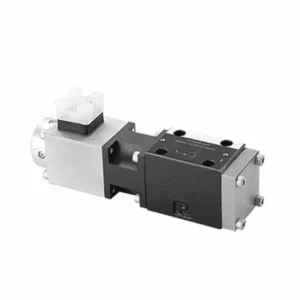
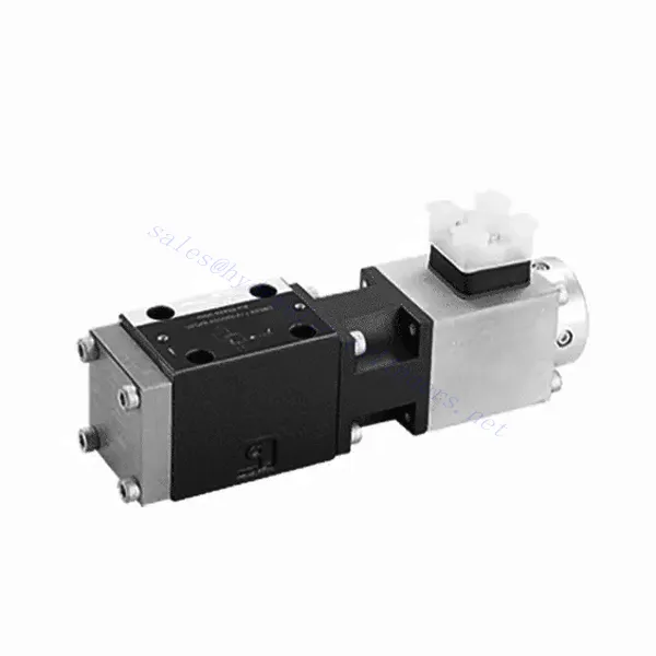
DBE6X(E) სერიის პროპორციული წნევის შემამსუბუქებელი ჰიდრავლიკური სარქველი წარმოადგენს ულტრათანამედროვე კომპონენტს, რომელიც უზრუნველყოფს ჰიდრავლიკურ სისტემებში წნევის ზუსტ და დინამიურ კონტროლს. მისი მოწინავე პროპორციული მართვის ტექნოლოგიით, ეს სარქველი უზრუნველყოფს ოპტიმალურ მუშაობას, ეფექტურობას და უსაფრთხოებას.
DBETX სერიის პროპორციული წნევის შემსუბუქების ჰიდრავლიკური სარქველი ჰიდრავლიკურ სისტემებს ანიჭებს წნევის ზუსტ კონტროლს, გაუმჯობესებულ ეფექტურობას და აღჭურვილობის დაცვას. მისი შესაბამისი წნევის შემსუბუქების შესაძლებლობებით, ეს სარქველი უზრუნველყოფს ოპტიმალურ მუშაობას სხვადასხვა დანიშნულებაში. რეკომენდებული გამოყენების მეთოდებისა და მოვლა-პატრონობის ინსტრუქციების დაცვით, თქვენ შეგიძლიათ მაქსიმალურად გამოიყენოთ DBETX სერიის სარქვლის სარგებელი და საიმედოობა, რითაც გაუმჯობესდება თქვენი ჰიდრავლიკური სისტემის მუშაობა და კონტროლი. განაახლეთ თქვენი ჰიდრავლიკური სისტემა დღესვე და განიცადეთ წნევის უმაღლესი დონის რეგულირება DBETX სერიის პროპორციული წნევის შემსუბუქების ჰიდრავლიკური სარქველით.
DBE6X (E) სერიის პროპორციული წნევის შემსუბუქების ჰიდრავლიკური სარქვლის ძირითადი მახასიათებლები:
- პროპორციული წნევის შემსუბუქება:
- DBE6X(E) სერიის სარქველი უზრუნველყოფს წნევის ზუსტ და პროპორციულ შემსუბუქებას, რაც საშუალებას იძლევა ჰიდრავლიკური წნევის დინამიური კონტროლის.
- ის უზრუნველყოფს წნევის ზუსტ რეგულირებას სხვადასხვა დატვირთვის პირობების საპასუხოდ, ხელს უშლის სისტემის გადატვირთვას და იცავს ჰიდრავლიკურ კომპონენტებს.
- გაუმჯობესებული სისტემის ეფექტურობა:
- ეს სარქველი უზრუნველყოფს ჰიდრავლიკური წნევის ზუსტ კონტროლს, რაც ზრდის სისტემის ეფექტურობას და ამცირებს ენერგიის მოხმარებას.
- სასურველი წნევის დონის შენარჩუნებით, ის მინიმუმამდე ამცირებს წნევის რყევებს, ოპტიმიზაციას უკეთებს სისტემის მუშაობას და ამცირებს საოპერაციო ხარჯებს.
- უსაფრთხოება და აღჭურვილობის დაცვა:
- DBE6X(E) სერიის სარქველი მოქმედებს როგორც დამცავი მექანიზმი ჰიდრავლიკურ სისტემაში წნევის შეზღუდვით, აღჭურვილობისა და ოპერატორების დაცვით.
- ეს ხელს უშლის ზედმეტი წნევის დაგროვებას, ამცირებს კომპონენტების დაზიანების, სისტემის გაუმართაობის და პოტენციური ავარიების რისკს.
- პროპორციული კონტროლის ფუნქციონალი:
- პროპორციული მართვის ტექნოლოგიით, DBE6X(E) სერიის სარქველი უზრუნველყოფს წნევის გლუვ და ზუსტ რეგულირებას.
- ის საშუალებას იძლევა რეალურ დროში წნევის კონტროლის, რაც უზრუნველყოფს სხვადასხვა ჰიდრავლიკურ სისტემასა და გამოყენებაში შეუფერხებელ ინტეგრაციას.
DBE6X (E) სერიის პროპორციული წნევის შემსუბუქების ჰიდრავლიკური სარქვლის პარამეტრი:
| ზოგადი | ||||||
| მშენებლობა | პილოტური ეტაპი | პოპეტური სარქველი | ||||
| მთავარი სცენა | კოჭის სარქველი | |||||
| აქტივაცია | პროპორციული სოლენოიდი პოზიციის კონტროლის გარეშე, გარე გამაძლიერებელი | |||||
| კავშირის ტიპი | ქვეფირფიტა, სამონტაჟო ხვრელის კონფიგურაცია NG6 (SIO 4401-03-02-094) | |||||
| ინსტალაციის პოზიცია | არასავალდებულო | |||||
| გარემოებები ტემპერატურის დიაპაზონი | ℃ | -20-დან +50-მდე | ||||
| წონა | კგ | 2.2 | ||||
| ვიბრაციის წინააღმდეგობა, ტესტის პირობები | მაქს. 25 გ, შერყევის შემდეგ 3 განზომილებაში (24 სთ) | |||||
| ჰიდრავლიკური (გაზომილი HLP 46-ით, ზეთი = 40℃ ± 5℃): | ||||||
| წნევის სითხე | ჰიდრავლიკური ზეთი DIN 51524…535-ის შესაბამისად, სხვა სითხეები წინასწარი კონსულტაციის შემდეგ | |||||
| სიბლანტის დიაპაზონი | რეკომენდებული | მმ²/წმ | 20…100 | |||
| მაქსიმუმ დაშვებული | მმ²/წმ | 10…800 | ||||
| წნევის სითხის ტემპერატურის დიაპაზონი | ℃ | -20-დან +80-მდე | ||||
| წნევის სითხის დაბინძურების მაქსიმალური დასაშვები ხარისხი. სისუფთავის კლასი ISO 4406 (c) სტანდარტის შესაბამისად. | კლასი 18/16/13 | |||||
| ნაკადის მიმართულება | იხილეთ სიმბოლო | |||||
| მაქსიმალური დაყენების წნევა (Qmaxx = 1 ლ/წთ-ზე) | ბარი | 80 | 180 | 250 | 315 | |
| მინ. დასაყენებელი წნევა (当 Qmin = 1 ლ/წთ) | ბარი | 7 | 8 | 9 | 10 | |
| მაქსიმალური სამუშაო წნევა | ბარი | პორტი P: 315 | ||||
| პორტი T: 250 | ||||||
| მექანიკური წნევის მაქსიმალური შეზღუდვის დონე, მაგ., როდესაც სოლენოიდის დენი I>Imax | ბარი | < 90 | < 190 | < 260 | < 235 | |
| პილოტური ზეთის ნაკადი | ლ/წთ | დაახლოებით 0.6 | ||||
| მაქსიმალური ნაკადის სიჩქარე | ლ/წთ | 40 | ||||
| ელექტრო მონაცემები | ||||||
| ციკლური ხანგრძლივობის კოეფიციენტი | % | 100 ED | ||||
| დაცვის ხარისხი | IP 65 DIN 40050-ის და IEC 14434/5-ის შესაბამისად | |||||
| სოლენოიდის შეერთება | DIN 43650/ISO 4400-ის შესაერთებელი, M16X1.5 (2P+PE) | |||||
| სოლენოიდის ტიპის სარქველი | 0.8A | 2.5A | ||||
| სოლენოიდის მაქსიმალური დენი | იმაქსი | 0.8A | 2.5A | |||
| ხვეულის წინააღმდეგობა R20 | ომეგა | 22 | 3 | |||
| მაქსიმალური ენერგომოხმარება 100% დატვირთვისა და სამუშაო ტემპერატურის დროს | ვეტერანთა საქმეების დეპარტამენტი | 25 | 30 | |||
| სტატიკური/დინამიური | ||||||
| ჰისტერეზისი | % | ≤ 4 | ||||
| ინვერსიის დიაპაზონი | % | ≤3 | ||||
| Pmax-ის წარმოების ტოლერანტობა | % | ≤10 | ||||
| რეაგირების დრო 100% სიგნალის ცვლილება | მილიწამი | ჩართულია 200 / გამორთულია | ||||
DBE6X (E) სერიის პროპორციული წნევის შემსუბუქების ჰიდრავლიკური სარქვლის უპირატესობები:
• სისტემის წნევის შესაზღუდავი პილოტური სარქველი (მხოლოდ შიდა ზეთის კონტროლისთვის)
• შესაძლებელია კოჭის დენის რეგულირება დამახასიათებელი მრუდისა და არჩეული ელექტრონული მართვის ბლოკის მიხედვით
• სოლენოიდის ტიპი Imax=0.8 A ან 2.5 A
• ელექტრონული მართვის ბლოკის გაუმართაობის შემთხვევაში, გადატვირთვისგან დაცვას შეუძლია იმუშაოს უმაღლესი ხარისხით (კოჭას დენი > Imax)
• გამოიყენება სარქვლის ქვეფირფიტის მონტაჟისთვის, სამონტაჟო ხვრელი შეესაბამება ISO 441-03-02-0-94 სტანდარტს,
• კაბელის ბუდეები შეესაბამება DIN 43650-AM2 სტანდარტს
• გარე ელექტრონული მართვის ბლოკი რამპადისა და სარქვლის რეგულირების ფუნქციით VT-SSPA1-508/525-L2X/V0/*
DBE6X (E) სერიის პროპორციული წნევის შემსუბუქების ჰიდრავლიკური სარქვლის გამოყენების მეთოდი:
- სისტემის შეფასება:
- შეაფასეთ თქვენი ჰიდრავლიკური სისტემა და დაადგინეთ წნევის კონტროლის სპეციფიკური მოთხოვნები.
- განსაზღვრეთ, თავსებადია თუ არა DBE6X(E) სერიის სარქველი თქვენს სისტემასთან მისი წნევის დიაპაზონის, ნაკადის სიმძლავრისა და სხვა სპეციფიკაციების მიხედვით.
- სარქვლის შერჩევა:
- აირჩიეთ DBE6X(E) სერიის შესაბამისი სარქვლის ვარიანტი თქვენი სისტემის პარამეტრების, წნევის დიაპაზონისა და ნაკადის მოთხოვნების საფუძველზე.
- გაითვალისწინეთ მაქსიმალური წნევის ნომინალური მაჩვენებელი, რეაგირების დრო და ოპერაციული პირობები.
- ინსტალაცია:
- ყურადღებით მიჰყევით მწარმოებლის ინსტალაციის ინსტრუქციებს, უზრუნველყავით სარქვლის სწორი გასწორება და უსაფრთხოდ დამაგრება.
- შეაერთეთ სარქველი ჰიდრავლიკურ სისტემასთან, უზრუნველყავით გაჟონვისგან თავისუფალი კავშირები და ნაკადის მიმართულების სწორი გასწორება.
- წნევის რეგულირება:
- სასურველი წნევის შემსუბუქების დონის დასაყენებლად გამოიყენეთ DBE6X(E) სერიის სარქველთან ერთად მოწოდებული პროპორციული მართვის სიგნალი ან რეგულირების მექანიზმი.
- წნევის ზუსტი კონტროლის მისაღწევად, სარქველი თანდათანობით დაარეგულირეთ, წნევის საზომის ჩვენებებისა და სისტემის რეაგირების მონიტორინგით.
როგორ დავარეგულიროთ ჰიდრავლიკური ნაკადის კონტროლის სარქველი?
ჰიდრავლიკური წნევის შემამსუბუქებელი სარქვლის რეგულირება საშუალებას გაძლევთ დააყენოთ სასურველი მაქსიმალური წნევა ჰიდრავლიკურ სისტემაში. ეს მნიშვნელოვანია სისტემის მთლიანობის შესანარჩუნებლად და კომპონენტების დაზიანების თავიდან ასაცილებლად. აქ მოცემულია ეტაპობრივი ინსტრუქცია, თუ როგორ უნდა დაარეგულიროთ ჰიდრავლიკური წნევის შემამსუბუქებელი სარქველი:
- წნევის შემამსუბუქებელი სარქვლის იდენტიფიცირება:
- იპოვეთ წნევის შემამსუბუქებელი სარქველი თქვენს ჰიდრავლიკურ სისტემაში. ის, როგორც წესი, დამონტაჟებულია ჰიდრავლიკურ ხაზში და ხშირად ტუმბოს ან მართვის სარქვლის მახლობლად.
- სარქვლის დიზაინის გაგება:
- გაეცანით იმ წნევის შემამსუბუქებელი სარქვლის სპეციფიკურ დიზაინს, რომელთანაც მუშაობთ. სხვადასხვა სარქველს შეიძლება ჰქონდეს განსხვავებული რეგულირების მექანიზმები, როგორიცაა სახელური, ხრახნი ან საკეტი ხრახნი.
- სასურველი წნევის განსაზღვრა:
- შეაფასეთ თქვენი ჰიდრავლიკური სისტემის მოთხოვნები და განსაზღვრეთ სასურველი მაქსიმალური წნევა. ეს დაგეხმარებათ წნევის შემამსუბუქებელი სარქვლის ზუსტად რეგულირებაში.
- სისტემის მომზადება:
- ნებისმიერი რეგულირების განხორციელებამდე გამორთეთ ჰიდრავლიკური სისტემა და შეამცირეთ წნევა მართვის ბერკეტების წინ და უკან გადაადგილებით ან მწარმოებლის მიერ რეკომენდებული პროცედურის დაცვით.
- იპოვეთ რეგულირების მექანიზმი:
- დაადგინეთ წნევის შემამსუბუქებელი სარქვლის რეგულირების მექანიზმი. ეს შეიძლება იყოს სახელური, ხრახნი ან საკეტი ხრახნი, რომელიც განთავსებულია სარქვლის კორპუსზე ან მის მიმდებარედ.
- სარქვლის რეგულირება:
- თუ სარქველს აქვს სახელური ან სახელური, წნევის შემსუბუქების პარამეტრის გასაზრდელად მოატრიალეთ ის საათის ისრის მიმართულებით, ხოლო შესამცირებლად - საათის ისრის საწინააღმდეგო მიმართულებით. თუ სარქველს აქვს ხრახნი, წნევის შემსუბუქების გასაზრდელად მოატრიალეთ ის საათის ისრის მიმართულებით, ხოლო შესამცირებლად - საათის ისრის საწინააღმდეგო მიმართულებით.
- თანდათანობითი კორექტირების განხორციელება:
- წნევის შემამსუბუქებელი სარქვლის რეგულირებისას, წნევის უეცარი ან მკვეთრი ცვალებადობის თავიდან ასაცილებლად, შეიტანეთ მცირე, თანდათანობითი ცვლილებები. ეს საშუალებას გაძლევთ დააზუსტოთ მაქსიმალური წნევა და მიაღწიოთ სასურველ მუშაობას.
- დააკვირდით სისტემას:
- თითოეული რეგულირებისას დააკვირდით ჰიდრავლიკურ სისტემას და მის კომპონენტებს. ყურადღება მიაქციეთ წნევის საზომის ჩვენებებს, რათა ნახოთ, ემთხვევა თუ არა ისინი სასურველ მაქსიმალურ წნევას.
- ტესტირება და გადამოწმება:
- ჰიდრავლიკური სისტემის მართვა და წნევის მონიტორინგი იმის უზრუნველსაყოფად, რომ ის სასურველ დიაპაზონში დარჩეს. შეამოწმეთ წნევის რყევები ან დარღვევები, რაც შეიძლება დამატებითი რეგულირების საჭიროებაზე მიუთითებდეს.
- რეგულირების დაბლოკვა:
- სასურველი წნევის შემსუბუქების პარამეტრის მიღწევის შემდეგ, დაუკრავენ რეგულირების მექანიზმს, რათა თავიდან აიცილოთ გაუთვალისწინებელი ცვლილებები. ზოგიერთ სარქველს შეიძლება ჰქონდეს დამამაგრებელი თხილი ან ხრახნი, რომლის გამკაცრებაც შესაძლებელია რეგულირების ადგილზე დასაფიქსირებლად.
- მონიტორინგი და ხელახლა დათვალიერება:
- რეგულარულად აკონტროლეთ წნევის შემამსუბუქებელი სარქველი და ჰიდრავლიკური სისტემა. თუ სისტემაში ცვლილებებია ან თუ სასურველი მაქსიმალური წნევის რეგულირებაა საჭირო, ხელახლა შეამოწმეთ წნევის შემამსუბუქებელი სარქველი და საჭიროებისამებრ გაიმეორეთ რეგულირების პროცესი.
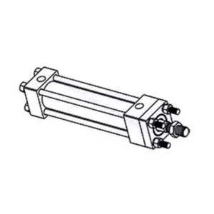
ქარხნის შესაძლებლობები და სიმძლავრე:
(1) აწყობა
ჩვენ გვაქვს პირველი კლასის დამოუკიდებელი კვლევისა და განვითარების აწყობის პლატფორმა. ჰიდრავლიკური ცილინდრების წარმოების სახელოსნოს აქვს ოთხი ნახევრად ავტომატური ამწევი ცილინდრების აწყობის ხაზი და ერთი ავტომატური დახრილი ცილინდრების აწყობის ხაზი, რომელთა წლიური წარმოების მოცულობა 1 მილიონი ცალია. სპეციალური ცილინდრების სახელოსნო აღჭურვილია სხვადასხვა სპეციფიკაციის ნახევრად ავტომატური საწმენდი აწყობის სისტემით, რომლის წლიური წარმოების მოცულობა 200,000 ცალია და აღჭურვილია ცნობილი CNC დამუშავების აღჭურვილობით, დამუშავების ცენტრით, მაღალი სიზუსტის ცილინდრების დამუშავების სპეციალური აღჭურვილობით, რობოტ-შედუღების დანადგარით, ავტომატური საწმენდი დანადგარით, ავტომატური ცილინდრების აწყობის დანადგარით და ავტომატური შეღებვის წარმოების ხაზით. არსებული კრიტიკული აღჭურვილობა 300-ზე მეტი კომპლექტით (კომპლექტით) შედგება. აღჭურვილობის რესურსების ოპტიმალური განაწილება და ეფექტური გამოყენება უზრუნველყოფს პროდუქციის სიზუსტის მოთხოვნებს და აკმაყოფილებს პროდუქციის მაღალი ხარისხის საჭიროებებს.


(2) დამუშავება
დამუშავების საამქრო აღჭურვილია ინდივიდუალურად მორგებული დახრილი რელსების შემობრუნების ცენტრით, დამუშავების ცენტრით, მაღალსიჩქარიანი დამუშავების დანადგარით, შედუღების რობოტით და სხვა დაკავშირებული აღჭურვილობით, რომელსაც შეუძლია ცილინდრული მილების დამუშავება მაქსიმალური შიდა დიამეტრით 400 მმ და მაქსიმალური სიგრძით 6 მეტრი.

(3) შედუღება

(4) შეღებვა და საფარი
მცირე და საშუალო ზომის ცილინდრიანი ავტომატური წყალზე დაფუძნებული საღებავის საფარის ხაზებით, ავტომატური რობოტის ჩატვირთვა-გადმოტვირთვისა და ავტომატური შესხურების მისაღწევად, ცვლაში 4000 ცალი დიზაინის ტევადობით;
ჩვენ ასევე გვაქვს ელექტრო ჯაჭვით მომუშავე ნახევრად ავტომატური საღებავის წარმოების ხაზი დიდი ცილინდრებისთვის, ცვლაში 60 ყუთის დამუშავების საპროექტო სიმძლავრით.


(5) ტესტირება
ჩვენ გვაქვს პირველი კლასის შემოწმების ობიექტები და სატესტო ცენტრები, რათა უზრუნველვყოთ, რომ ცილინდრის მუშაობა აკმაყოფილებს მოთხოვნებს.

ჩვენ ვართ ერთ-ერთი საუკეთესო ჰიდრავლიკური ცილინდრების მწარმოებელი. ჩვენ შეგვიძლია შემოგთავაზოთ ჰიდრავლიკური ცილინდრების ყოვლისმომცველი ნაკრები. ჩვენ ასევე ვთავაზობთ შესაბამის... სასოფლო-სამეურნეო გადაცემათა კოლოფიჩვენ ჩვენი პროდუქცია მსოფლიოს მასშტაბით კლიენტებისთვის ექსპორტირებული გვაქვს და კარგი რეპუტაცია დავიმსახურეთ ჩვენი უმაღლესი ხარისხისა და გაყიდვის შემდგომი მომსახურების წყალობით. ჩვენ მივესალმებით როგორც ადგილობრივ, ასევე საზღვარგარეთელ მომხმარებლებს, რომლებიც დაგვიკავშირდებიან ბიზნესთან დაკავშირებით მოლაპარაკებების, ინფორმაციის გაცვლისა და ითანამშრომლეთ ჩვენთან!