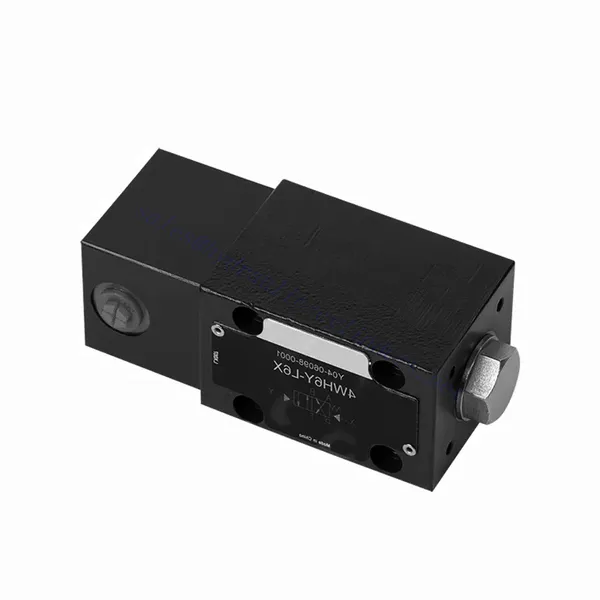
WH(D) Series Directional Hydraulic Valve With Fluidic Actuation
WH(D) Series Directional Hydraulic Valve With Fluidic Actuation
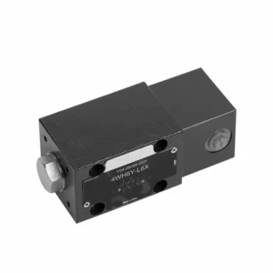
The WH(D) series directional hydraulic valve with fluidic actuation is a state-of-the-art product designed to provide precise control and efficient operation in hydraulic systems. With its advanced features and reliable performance, this valve offers enhanced functionality and versatility.
The WH(D)series directional hydraulic valve with fluidic actuation offers advanced control and efficiency for hydraulic systems. Its fluidic actuation mechanism, precise directional control, and high flow capacity enhance functionality and versatility. Following the recommended usage methods and adhering to regular maintenance practices, the WH(D) series valve will continue delivering efficient and reliable operation. Upgrade your hydraulic system with the WH(D) series directional hydraulic valve and experience the benefits of enhanced control and efficiency.
WH(D) Series Directional Hydraulic Valve With Fluidic Actuation Key Characteristics:
- Fluidic Actuation:
- The WH(D) series valve utilizes fluidic actuation, allowing for precise and responsive fluid flow control within hydraulic systems.
- This actuation method offers improved accuracy and efficiency compared to traditional mechanisms.
- მიმართულების კონტროლი:
- This hydraulic valve enables precise directional control of fluid flow, allowing operators to select the desired flow path easily.
- Directing the hydraulic fluid to the appropriate actuators or components ensures efficient and reliable operation.
- მაღალი ნაკადის ტევადობა:
- The WH(D) Series Valve is designed to handle high flow rates, making it suitable for applications that require substantial fluid flow.
- Its robust construction and optimized internal passages ensure smooth flow and minimal pressure drop.
- მრავალფეროვნება:
- This valve is highly versatile and can be used in various industries and applications, such as manufacturing, construction, agriculture, etc.
- It can be integrated into hydraulic systems that require precise control and efficient fluid management.
WH(D) Series Directional Hydraulic Valve With Fluidic Actuation Parameter:
NG6
| ინსტალაციის პოზიცია | არასავალდებულო | ||
| სითხის ტემპერატურის დიაპაზონი | ℃ | -30 to +80 (NBR seals) | |
| -20 to +80 (FKM seals) | |||
| Port Max. operating pressure | Port A B P | ბარი | 315 |
| პორტი T | ბარი | 60 | |
| მაქსიმალური ნაკადის სიჩქარე | ლ/წთ | 60 | |
| Flow cross section (switching neutral position) | Q type | მმ2 | For symbol Q, 6% of the nominal cross-section |
| W type | მმ2 | For symbol W, 3% of the nominal cross-section | |
| სითხე | მინერალური ზეთი; ფოსფატის ეთერი | ||
| სიბლანტის დიაპაზონი | მმ2/წმ | 2.8-დან 500-მდე | |
| დაბინძურების ხარისხი | სითხის დაბინძურების მაქსიმალური დასაშვები ხარისხი: კლასი 9. NAS 1638 ან 20/18/15, ISO4406 | ||
| წონა | კგ | 1.4 | |
NG10
| ინსტალაციის პოზიცია | არასავალდებულო | ||
| სითხის ტემპერატურის დიაპაზონი | ℃ | -30 to +80 (NBR seals) | |
| -20 to +80 (FKM seals) | |||
| Port Max. operating pressure | Port A B P | ბარი | 315 |
| პორტი T | ბარი | 60 | |
| მაქსიმალური ნაკადის სიჩქარე | ლ/წთ | 120 | |
| Flow cross section (switching neutral position) | V type | მმ2 | 11(A/B → T); 10.3(P → A/B) |
| W type | მმ2 | 2.5 (A/B → T) | |
| Q type | მმ2 | 5.5 (A/B → T) | |
| სითხე | მინერალური ზეთი; ფოსფატის ეთერი | ||
| სიბლანტის დიაპაზონი | მმ2/წმ | 2.8-დან 500-მდე | |
| დაბინძურების ხარისხი | სითხის დაბინძურების მაქსიმალური დასაშვები ხარისხი: კლასი 9. NAS 1638 ან 20/18/15, ISO4406 | ||
| წონა | კგ | 4 | |
WH(D) Series Directional Hydraulic Valve With Fluidic Actuation Advantages:
• Direct-acting directional slide valve direct-acting directional slide valve
• Scroll wheel can rotate 90°
• Nineteen standard slide valve functions
Usage Method Of WH(D) Series Directional Hydraulic Valve With Fluidic Actuation:
- სისტემის ინტეგრაცია:
- Identify the optimal location for the WH(D) series valve within the hydraulic system, considering the desired flow path and control requirements.
- უზრუნველყავით თავსებადობა სისტემის წნევისა და ნაკადის სპეციფიკაციებთან.
- Mount the valve securely using appropriate brackets or mounting accessories.
- სითხის შეერთებები:
- უსაფრთხო და გაჟონვისგან თავისუფალი შეერთებებისთვის შეარჩიეთ თავსებადი ჰიდრავლიკური ფიტინგები და შლანგები.
- ინსტალაციის პროცესში დაიცავით მწარმოებლის ინსტრუქციები ბრუნვის მომენტის სწორი მნიშვნელობებისთვის.
- საიმედო დალუქვის უზრუნველსაყოფად გამოიყენეთ შესაბამისი ძაფის დალუქვის საშუალებები ან ლენტი.
- Actuation:
- Familiarize yourself with the fluidic actuation mechanism of the valve and understand the control methods available.
- Connect the actuation lines to the designated ports, ensuring proper identification and connection integrity.
- კონტროლი და რეგულირება:
- Employ the recommended control method, such as manual levers, solenoid valves, or other actuation devices, to operate the WH(D) Series Valve.
- Adjust the valve settings according to the desired flow direction and flow rates, ensuring optimal performance.
How A Hydraulic Valve Works?
A hydraulic valve is a critical component in a hydraulic system that controls the flow and direction of hydraulic fluid. It allows operators to regulate the movement and pressure of the liquid, enabling precise control over various hydraulic functions. Here’s a simplified explanation of how a hydraulic valve works:
- სარქვლის სტრუქტურა:
- A hydraulic valve typically consists of a valve body, which houses various internal components such as ports, chambers, and passages.
- The valve body also contains movable parts, such as spools or poppets, which control the flow of hydraulic fluid.
- Fluid Flow:
- Hydraulic valves have multiple ports that connect to different sections of the hydraulic system.
- The hydraulic fluid enters the valve through an inlet port and flows through internal passages within the valve body.
- კოჭის ან პოპეტის მოძრაობა:
- A spool or poppet mechanism controls the movement of the hydraulic valve.
- The spool is a cylindrical component with lands or grooves machined into its surface, while a poppet is a movable plug-like element.
- When the spool or poppet is in a specific position, it allows hydraulic fluid to flow through certain passages and blocks others.
- სარქვლის გააქტიურება:
- Hydraulic valves can be actuated in various ways, such as manual levers, solenoids, or pilot control.
- Actuation mechanisms control the position of the spool or poppet, determining which passages are opened or closed.
- Manual valves are operated by hand, while solenoid valves use an electrical signal to move the spool or poppet.
- Flow Direction and Control:
- By adjusting the position of the spool or poppet, hydraulic valves can control the direction of fluid flow.
- For example, in a directional control valve, the spool’s position determines whether fluid flows from the inlet to the outlet or is redirected to other ports.
- Other hydraulic valves, such as pressure control or flow control valves, regulate the fluid pressure or flow rate respectively.
- წნევის კომპენსაცია:
- Hydraulic valves often incorporate pressure compensation mechanisms to maintain a consistent pressure within the system.
- These mechanisms ensure that the valve adjusts to changes in pressure and maintains the desired flow rate or pressure level.
- Return or Exhaust:
- In some hydraulic systems, valves provide a return or exhaust path for hydraulic fluid.
- These valves enable the controlled release or redirection of fluid back to the reservoir when it is no longer required in a particular circuit.
ქარხნის შესაძლებლობები და სიმძლავრე:
(1) აწყობა
ჩვენ გვაქვს პირველი კლასის დამოუკიდებელი კვლევისა და განვითარების აწყობის პლატფორმა. ჰიდრავლიკური ცილინდრების წარმოების სახელოსნოს აქვს ოთხი ნახევრად ავტომატური ამწევი ცილინდრების აწყობის ხაზი და ერთი ავტომატური დახრილი ცილინდრების აწყობის ხაზი, რომელთა წლიური წარმოების მოცულობა 1 მილიონი ცალია. სპეციალური ცილინდრების სახელოსნო აღჭურვილია სხვადასხვა სპეციფიკაციის ნახევრად ავტომატური საწმენდი აწყობის სისტემით, რომლის წლიური წარმოების მოცულობა 200,000 ცალია და აღჭურვილია ცნობილი CNC დამუშავების აღჭურვილობით, დამუშავების ცენტრით, მაღალი სიზუსტის ცილინდრების დამუშავების სპეციალური აღჭურვილობით, რობოტ-შედუღების დანადგარით, ავტომატური საწმენდი დანადგარით, ავტომატური ცილინდრების აწყობის დანადგარით და ავტომატური შეღებვის წარმოების ხაზით. არსებული კრიტიკული აღჭურვილობა 300-ზე მეტი კომპლექტით (კომპლექტით) შედგება. აღჭურვილობის რესურსების ოპტიმალური განაწილება და ეფექტური გამოყენება უზრუნველყოფს პროდუქციის სიზუსტის მოთხოვნებს და აკმაყოფილებს პროდუქციის მაღალი ხარისხის საჭიროებებს.


(2) დამუშავება
დამუშავების საამქრო აღჭურვილია ინდივიდუალურად მორგებული დახრილი რელსების შემობრუნების ცენტრით, დამუშავების ცენტრით, მაღალსიჩქარიანი დამუშავების დანადგარით, შედუღების რობოტით და სხვა დაკავშირებული აღჭურვილობით, რომელსაც შეუძლია ცილინდრული მილების დამუშავება მაქსიმალური შიდა დიამეტრით 400 მმ და მაქსიმალური სიგრძით 6 მეტრი.

(3) შედუღება

(4) შეღებვა და საფარი
მცირე და საშუალო ზომის ცილინდრიანი ავტომატური წყალზე დაფუძნებული საღებავის საფარის ხაზებით, ავტომატური რობოტის ჩატვირთვა-გადმოტვირთვისა და ავტომატური შესხურების მისაღწევად, ცვლაში 4000 ცალი დიზაინის ტევადობით;
ჩვენ ასევე გვაქვს ელექტრო ჯაჭვით მომუშავე ნახევრად ავტომატური საღებავის წარმოების ხაზი დიდი ცილინდრებისთვის, ცვლაში 60 ყუთის დამუშავების საპროექტო სიმძლავრით.


(5) ტესტირება
ჩვენ გვაქვს პირველი კლასის შემოწმების ობიექტები და სატესტო ცენტრები, რათა უზრუნველვყოთ, რომ ცილინდრის მუშაობა აკმაყოფილებს მოთხოვნებს.

ჩვენ ვართ ერთ-ერთი საუკეთესო ჰიდრავლიკური ცილინდრების მწარმოებელი. ჩვენ შეგვიძლია შემოგთავაზოთ ჰიდრავლიკური ცილინდრების ყოვლისმომცველი ნაკრები. ჩვენ ასევე ვთავაზობთ შესაბამის... სასოფლო-სამეურნეო გადაცემათა კოლოფიჩვენ ჩვენი პროდუქცია მსოფლიოს მასშტაბით კლიენტებისთვის ექსპორტირებული გვაქვს და კარგი რეპუტაცია დავიმსახურეთ ჩვენი უმაღლესი ხარისხისა და გაყიდვის შემდგომი მომსახურების წყალობით. ჩვენ მივესალმებით როგორც ადგილობრივ, ასევე საზღვარგარეთელ მომხმარებლებს, რომლებიც დაგვიკავშირდებიან ბიზნესთან დაკავშირებით მოლაპარაკებების, ინფორმაციის გაცვლისა და ითანამშრომლეთ ჩვენთან!