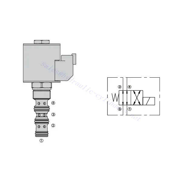
30SD10-40 솔레노이드 방향 밸브
30SD10-40 솔레노이드 방향 밸브
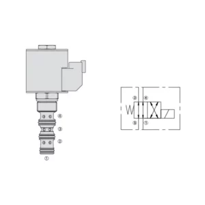
The 30SD10-40 solenoid directional valve is a high-performance industrial component designed to deliver precise and reliable fluid control in a variety of applications. With its advanced features, durable construction, and user-friendly design, this solenoid directional valve offers enhanced efficiency and operational reliability.
The 30SD10-40 solenoid directional valve is a reliable and versatile component that offers precise fluid control in industrial applications. Its robust construction, precision control, and reliable performance enhance efficiency and productivity in fluid control systems. By following the recommended usage methods and maintenance guidelines, you can ensure optimal performance and longevity of the 30SD10-40 solenoid directional valve in your industrial operations.
30SD10-40 Solenoid Directional Valve Characteristics:
- Robust Construction: The 30SD10-40 solenoid directional valve is built with exceptional craftsmanship and high-quality materials, ensuring durability and longevity. Its sturdy construction allows it to withstand demanding industrial environments, providing reliable performance even in harsh conditions.
- Versatile Functionality: This solenoid directional valve offers versatile functionality, making it suitable for a wide range of applications. It effectively controls the direction of fluid flow, enabling precise and efficient operation in various industrial systems.
- Precision Control: The 30SD10-40 solenoid directional valve provides exceptional precision in fluid control. It allows for accurate regulation and adjustment of fluid direction and pressure, ensuring optimal performance and efficiency in industrial processes.
- Reliable Performance: This solenoid directional valve delivers reliable performance, minimizing the risk of system failures or interruptions. It operates with dependability, contributing to increased productivity and reduced downtime in industrial operations.
30SD10-40 Solenoid Directional Valve Parameter:
| 정격 압력 | 207바(3000psi) | |
| 피크 유량 | 23L/분(6gpm) | |
| 체액 | 윤활성이 있는 광물 기반 또는 합성물 | |
| Temperature range ℃ | -54 ~ 107℃ (폴리우레탄 씰) | |
| -40 ~ 100℃ (부나 N 씰) | ||
| -26 ~ 204℃ (플루오로카본 씰) | ||
| 점도 범위 | 7.4~420mm2/에스 | |
| 오염 정도 | 최소 오염 수준은 ISO4406 레벨 20/18/14이며, 서비스 수명을 연장하기 위해 레벨 17/15/13이 권장됩니다. | |
| 내부 누출 | ≤ 82 mL/min@207bar | |
| 공동 | VC10-4 | |
| 코일 듀티 정격 | 정격전압 85%에서 115%까지 연속 | |
| 20℃에서의 초기 코일 전류 소모 | 전자코일 | 12VDC에서 1.7A, 24VDC에서 0.85A |
| D-코일 | 12VDC에서 1.67A, 24VDC에서 0.83A | |
| 최소 풀인 전압 | 207bar에서 공칭 85% | |
30SD10-40 Solenoid Directional Valve Advantages:
• 연속 사용 정격 코일
• 카트리지는 전압 교환이 가능합니다.
• 최대 IP69K 등급의 방수 E-코일 옵션
• 효율적인 습식 전기자 구조
• 산업 공통 공동
• 긴 수명을 위한 강화된 부품
Usage Method Of 30SD10-40 Solenoid Directional Valve :
- Integration into the System: Integrate the 30SD10-40 Solenoid Directional Valve into the fluid control system following the manufacturer’s guidelines and specifications. Ensure proper alignment and connection between the valve and other system components to achieve optimal performance.
- Electrical Connection: Establish a secure electrical connection for the solenoid directional valve. Follow the provided wiring diagram and ensure correct polarity to prevent electrical malfunctions. Adhere to safety guidelines when working with electrical connections.
- Fluid Flow Direction Control: Utilize the solenoid directional valve to control the direction of fluid flow. The valve is typically equipped with a lever or actuator for manual adjustment. Alternatively, it can be integrated into an automated control system for remote operation.
- Pressure Adjustment: Use the solenoid directional valve to regulate fluid pressure within the system. Adjust the valve’s settings to achieve the desired pressure levels for optimal performance and efficiency.
How To Read Hydraulic Valve Schematics?
Reading hydraulic valve schematics requires a basic understanding of hydraulic symbols and their meanings. Here are the steps to help you read hydraulic valve schematics:
- Familiarize Yourself With Hydraulic Symbols: Hydraulic schematics use graphical symbols to represent various components and functions. Common symbols include squares for valves, lines for pipes or hoses, arrows for flow direction, and circles for pressure or flow control devices. Make sure you understand the meaning of these symbols before proceeding.
- Identify The Valve Types: Look for the valve symbols in the schematic. Valves can be represented by squares with different shapes and orientations. For example, a square with a diagonal line represents a check valve, while a square with an arrow inside denotes a directional control valve.
- Determine The Valve Function: Each valve symbol indicates its specific function. Directional control valves determine the flow direction of hydraulic fluid, while pressure control valves regulate pressure levels. Flow control valves manage the rate of fluid flow, and check valves allow flow in one direction only.
- Observe The Valve Connections: Pay attention to the lines or arrows entering and exiting the valve symbol. These lines represent the hydraulic fluid flow paths. Arrows indicate the flow direction, and lines connecting valves and other components indicate the connections.
- Analyze The Valve Ositions: Some hydraulic valve schematics include symbols to illustrate the valve positions. These symbols typically depict the valve spool or lever in different positions, such as open, closed, or partially open. Understanding the valve positions helps you determine the flow paths and the state of the hydraulic system.
- Consider Additional Symbols And Annotations: Hydraulic schematics may include additional symbols and annotations to indicate pressure gauges, flow meters, filters, accumulators, or other components. Familiarize yourself with these symbols and their meanings to gain a comprehensive understanding of the system.
- Follow The Flow Paths: Trace the flow paths from the hydraulic power source through the various valves and components to the actuator or desired output. Understand how the valves interact with one another and how they control fluid flow, pressure, and direction to achieve the desired system operation.
- Refer To The Legend Or Key: The schematic should have a legend or key that explains the meaning of each symbol used in the diagram. If you encounter unfamiliar symbols or have doubts about their meaning, refer to the legend for clarification.
- Seek Additional Resources If Needed: If you need a more in-depth understanding of hydraulic valve schematics, consider referring to hydraulic textbooks, online resources, or consulting with hydraulic experts who can provide guidance and explanations tailored to your specific needs.
공장의 역량 및 용량:
(1) 조립
당사는 최고 수준의 독자적인 연구개발 조립 플랫폼을 보유하고 있습니다. 유압 실린더 생산 작업장은 4개의 반자동 리프팅 실린더 조립 라인과 1개의 자동 틸트 실린더 조립 라인을 갖추고 있으며, 연간 100만 개의 설계 생산 능력을 갖추고 있습니다. 특수 실린더 작업장은 다양한 사양의 반자동 세척 조립 시스템을 갖추고 있으며, 연간 20만 개의 설계 생산 능력을 갖추고 있습니다. 또한, 유명 CNC 가공 장비, 머시닝 센터, 고정밀 실린더 가공 특수 장비, 로봇 용접기, 자동 세척기, 자동 실린더 조립기, 자동 도장 생산 라인을 갖추고 있습니다. 300대 이상의 핵심 장비를 보유하고 있으며, 장비 자원의 최적 배치 및 효율적인 사용을 통해 제품의 정밀성 요구 사항을 충족하고 고품질 요구를 충족합니다.


(2) 가공
가공공장은 맞춤형 경사레일 터닝센터, 가공센터, 고속 호닝머신, 용접로봇 및 기타 관련 장비를 갖추고 있으며, 최대 내경 400mm, 최대 길이 6m의 원통형 튜브를 가공할 수 있습니다.

(3) 용접

(4) 도장 및 코팅
소형, 중형 실린더 자동 수성 페인트 코팅 라인을 통해 자동 로봇 로딩 및 언로딩과 자동 분무를 실현하며, 교대당 4000개의 설계 용량을 달성합니다.
또한, 우리는 60개의 케이스를 교대로 생산할 수 있는 설계 용량을 갖춘 파워 체인으로 구동되는 대형 실린더용 반자동 페인트 생산 라인을 보유하고 있습니다.


(5) 테스트
당사는 실린더의 성능이 요구 사항을 충족하는지 확인하기 위해 일류 검사 시설과 테스트 베드를 갖추고 있습니다.

저희는 최고의 유압 실린더 제조업체 중 하나입니다. 다양한 유압 실린더를 공급할 수 있으며, 관련 제품도 제공합니다. 농업용 기어박스저희는 전 세계 고객에게 제품을 수출해 왔으며, 탁월한 제품 품질과 애프터서비스를 통해 좋은 평판을 얻고 있습니다. 국내외 고객 여러분의 사업 상담, 정보 교환, 그리고 우리와 협력하다!