30SD10-40 Solenoid Directional Valve
30SD10-40 Solenoid Directional Valve
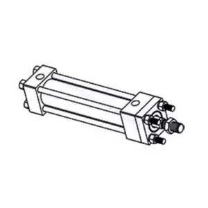
The 30SD10-40 solenoid directional valve is a high-performance industrial component designed to deliver precise and reliable fluid control in a variety of applications. With its advanced features, durable construction, and user-friendly design, this solenoid directional valve offers enhanced efficiency and operational reliability.
The 30SD10-40 solenoid directional valve is a reliable and versatile component that offers precise fluid control in industrial applications. Its robust construction, precision control, and reliable performance enhance efficiency and productivity in fluid control systems. By following the recommended usage methods and maintenance guidelines, you can ensure optimal performance and longevity of the 30SD10-40 solenoid directional valve in your industrial operations.
30SD10-40 Solenoid Directional Valve Characteristics:
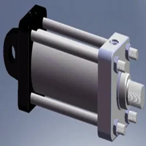
- Robust Construction: The 30SD10-40 solenoid directional valve is built with exceptional craftsmanship and high-quality materials, ensuring durability and longevity. Its sturdy construction allows it to withstand demanding industrial environments, providing reliable performance even in harsh conditions.
- Versatile Functionality: This solenoid directional valve offers versatile functionality, making it suitable for a wide range of applications. It effectively controls the direction of fluid flow, enabling precise and efficient operation in various industrial systems.
- Precision Control: The 30SD10-40 solenoid directional valve provides exceptional precision in fluid control. It allows for accurate regulation and adjustment of fluid direction and pressure, ensuring optimal performance and efficiency in industrial processes.
- Reliable Performance: This solenoid directional valve delivers reliable performance, minimizing the risk of system failures or interruptions. It operates with dependability, contributing to increased productivity and reduced downtime in industrial operations.
30SD10-40 Solenoid Directional Valve Parameter:
| Nazivni tlak | 207 barov (3000 psi) | |
| Najvišji pretok | 23 l/min (6 gpm) | |
| Tekočina | Mineralna ali sintetična olja z mazalnimi lastnostmi | |
| Temperature range ℃ | -54 do 107 ℃ (poliuretanska tesnila) | |
| -40 do 100 ℃ (tesnila Buna N) | ||
| -26 do 204 ℃ (tesnila iz fluoroogljika) | ||
| Območje viskoznosti | 7,4 do 420 mm2/s | |
| Stopnja kontaminacije | Najnižja stopnja onesnaženosti je po standardu ISO4406 20/18/14, za podaljšanje življenjske dobe pa je priporočljiva stopnja 17/15/13. | |
| Notranje puščanje | ≤ 82 mL/min@207bar | |
| Votlina | VC10-4 | |
| Nazivna obremenitev tuljave | Neprekinjeno od 85% do 115% nazivne napetosti | |
| Začetni tok tuljave pri 20 ℃ | E-tuljava | 1,7 A pri 12 V enosmernem toku; 0,85 A pri 24 V enosmernem toku |
| D-tuljava | 1,67 A pri 12 V enosmernem toku; 0,83 A pri 24 V enosmernem toku | |
| Minimalna vklopna napetost | 85% of nominal at 207 bar | |
30SD10-40 Solenoid Directional Valve Advantages:
• Tuljava za neprekinjeno delovanje
• Kartuše so zamenljive glede na napetost
• Izbirne vodoodporne e-tuljave z zaščito do IP69K
• Učinkovita konstrukcija z mokro armaturo
• Industrijska običajna votlina
• Kaljeni deli za dolgo življenjsko dobo
Usage Method Of 30SD10-40 Solenoid Directional Valve :
- Integration into the System: Integrate the 30SD10-40 Solenoid Directional Valve into the fluid control system following the manufacturer’s guidelines and specifications. Ensure proper alignment and connection between the valve and other system components to achieve optimal performance.
- Electrical Connection: Establish a secure electrical connection for the solenoid directional valve. Follow the provided wiring diagram and ensure correct polarity to prevent electrical malfunctions. Adhere to safety guidelines when working with electrical connections.
- Nadzor smeri pretoka tekočine: Za nadzor smeri pretoka tekočine uporabite elektromagnetni smerni ventil. Ventil je običajno opremljen z ročico ali aktuatorjem za ročno nastavitev. Lahko pa ga integrirate v avtomatiziran krmilni sistem za daljinsko upravljanje.
- Pressure Adjustment: Use the solenoid directional valve to regulate fluid pressure within the system. Adjust the valve’s settings to achieve the desired pressure levels for optimal performance and efficiency.
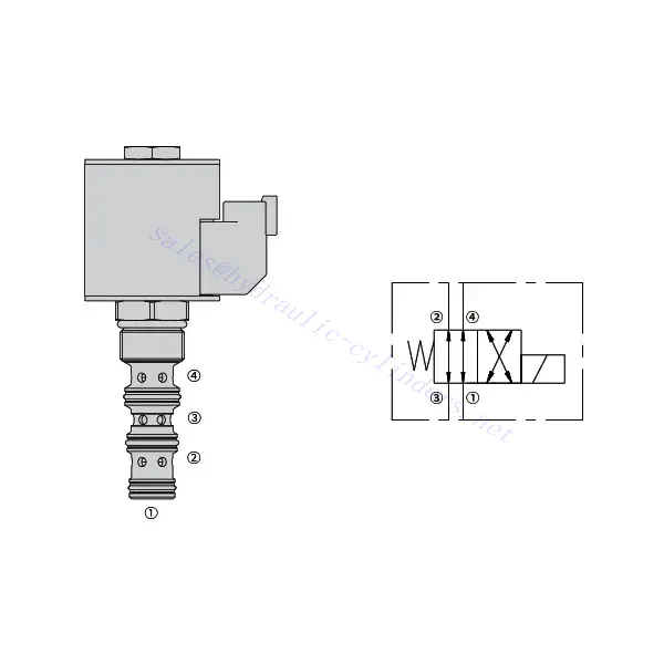
How To Read Hydraulic Valve Schematics?
Reading hydraulic valve schematics requires a basic understanding of hydraulic symbols and their meanings. Here are the steps to help you read hydraulic valve schematics:
- Familiarize Yourself With Hydraulic Symbols: Hydraulic schematics use graphical symbols to represent various components and functions. Common symbols include squares for valves, lines for pipes or hoses, arrows for flow direction, and circles for pressure or flow control devices. Make sure you understand the meaning of these symbols before proceeding.
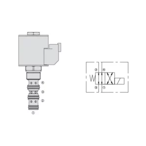
- Identify The Valve Types: Look for the valve symbols in the schematic. Valves can be represented by squares with different shapes and orientations. For example, a square with a diagonal line represents a check valve, while a square with an arrow inside denotes a directional control valve.
- Determine The Valve Function: Each valve symbol indicates its specific function. Directional control valves determine the flow direction of hydraulic fluid, while pressure control valves regulate pressure levels. Flow control valves manage the rate of fluid flow, and check valves allow flow in one direction only.
- Observe The Valve Connections: Pay attention to the lines or arrows entering and exiting the valve symbol. These lines represent the hydraulic fluid flow paths. Arrows indicate the flow direction, and lines connecting valves and other components indicate the connections.
- Analyze The Valve Ositions: Some hydraulic valve schematics include symbols to illustrate the valve positions. These symbols typically depict the valve spool or lever in different positions, such as open, closed, or partially open. Understanding the valve positions helps you determine the flow paths and the state of the hydraulic system.
- Consider Additional Symbols And Annotations: Hydraulic schematics may include additional symbols and annotations to indicate pressure gauges, flow meters, filters, accumulators, or other components. Familiarize yourself with these symbols and their meanings to gain a comprehensive understanding of the system.
- Follow The Flow Paths: Trace the flow paths from the hydraulic power source through the various valves and components to the actuator or desired output. Understand how the valves interact with one another and how they control fluid flow, pressure, and direction to achieve the desired system operation.
- Refer To The Legend Or Key: The schematic should have a legend or key that explains the meaning of each symbol used in the diagram. If you encounter unfamiliar symbols or have doubts about their meaning, refer to the legend for clarification.
- Seek Additional Resources If Needed: If you need a more in-depth understanding of hydraulic valve schematics, consider referring to hydraulic textbooks, online resources, or consulting with hydraulic experts who can provide guidance and explanations tailored to your specific needs.
Zmogljivost in zmogljivost tovarne:
(1) Sestavljanje
Imamo prvovrstno neodvisno platformo za raziskave in razvoj. Delavnica za proizvodnjo hidravličnih cilindrov ima štiri polavtomatske montažne linije za dvižne cilindre in eno avtomatsko montažno linijo za nagibne cilindre z letno proizvodno zmogljivostjo 1 milijona kosov. Delavnica za posebne cilindre je opremljena z različnimi specifikacijami polavtomatskega sistema za čiščenje in montažo z letno proizvodno zmogljivostjo 200.000 kosov ter znano CNC obdelovalno opremo, obdelovalnim centrom, visoko precizno posebno opremo za obdelavo cilindrov, robotskim varilnim strojem, avtomatskim čistilnim strojem, avtomatskim strojem za montažo cilindrov in avtomatsko proizvodno linijo za barvanje. Obstoječa kritična oprema obsega več kot 300 kompletov (kompletov). Optimalna razporeditev in učinkovita uporaba opremnih virov zagotavljata zahteve glede natančnosti izdelkov in izpolnjujeta visoke zahteve glede kakovosti izdelkov.


(2) Strojna obdelava
Strojna delavnica je opremljena s prilagojenim centrom za struženje nagnjenih tirnic, obdelovalnim centrom, visokohitrostnim strojem za honanje, varilnim robotom in drugo sorodno opremo, ki lahko obdeluje cilindrične cevi z največjim notranjim premerom 400 mm in največjo dolžino 6 metrov.

(3) Varjenje

(4) Barvanje in premazovanje
Z majhnimi in srednje velikimi cilindričnimi avtomatskimi linijami za barvanje na vodni osnovi, za doseganje avtomatskega nakladanja in razkladanja robotov ter avtomatskega brizganja, je projektna zmogljivost 4000 kosov na izmeno;
Imamo tudi polavtomatsko linijo za proizvodnjo barv za velike jeklenke, ki jo poganja veriga, s projektno zmogljivostjo 60 zabojev na izmeno.


(5) Testiranje
Imamo prvovrstne inšpekcijske prostore in testne postaje, s katerimi zagotavljamo, da delovanje jeklenke izpolnjuje zahteve.

Smo eden najboljših proizvajalcev hidravličnih cilindrov. Ponujamo vam celovite hidravlične cilindre. Zagotavljamo tudi ustrezne kmetijski menjalnikiNaše izdelke smo izvozili strankam po vsem svetu in si prislužili dober ugled zaradi vrhunske kakovosti izdelkov in poprodajnih storitev. Z veseljem vas vabimo, da nas kontaktirate za poslovne dogovore, izmenjavo informacij in ... sodelujte z nami!