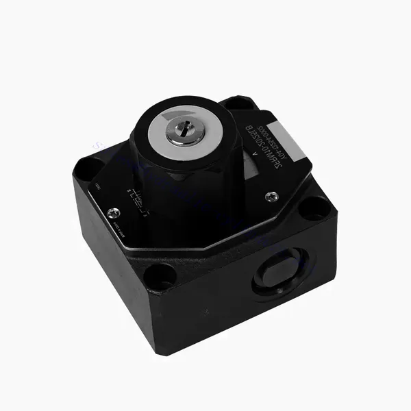
FRM 시리즈 유량 제어 유압 밸브
FRM 시리즈 유량 제어 유압 밸브
The FRM series flow control hydraulic valve is a cutting-edge hydraulic component designed to enhance the performance and control of hydraulic systems. With its advanced features and reliable functionality, this valve offers precise flow control and optimal efficiency.
The FRM series flow control hydraulic valve is a reliable and versatile solution for optimizing flow control in hydraulic systems. With its precise flow control capabilities, pressure and temperature stability, and durable construction, this valve offers enhanced performance and efficiency. Following the recommended usage methods and maintenance guidelines, operators can maximize the benefits of the FRM series flow control hydraulic valve, ensuring smooth operation and reliable flow control in their hydraulic applications. Upgrade your hydraulic system with this advanced valve and experience precision, efficiency, and productivity like never before.
FRM Series Flow Control Hydraulic Valve Key Characteristics:
- Flow Control Precision:
- The FRM series valve enables precise control over the flow rate of hydraulic fluids, allowing operators to fine-tune and regulate the speed of actuators.
- With its exceptional accuracy, this valve ensures consistent flow control, resulting in improved system performance and enhanced productivity.
- 다양한 응용 분야:
- The FRM series valve is highly versatile and compatible with various hydraulic systems, including industrial machinery, construction equipment, and mobile applications.
- Its adaptability makes it an ideal choice for a wide range of hydraulic setups, providing reliable and efficient flow control.
- Pressure and Temperature Stability:
- This hydraulic valve is designed to maintain consistent flow control even under varying pressure and temperature conditions.
- It ensures stable performance and prevents flow fluctuations, safeguarding the integrity and reliability of the hydraulic system.
- 내구성 있는 구조:
- The FRM series valve is constructed with high-quality materials, ensuring durability and long-term reliability in demanding operating environments.
- Its robust design allows it to withstand high pressures, vibrations, and temperature extremes, providing a dependable solution for hydraulic applications.
FRM Series Flow Control Hydraulic Valve Parameter:
NG6
| Flow control valve | |||||||||||
| Max. operating pressure-Port A | 술집 | 315 | |||||||||
| Pressure differential ΔP for free return flow B to A | 특성 곡선을 참조하세요 | ||||||||||
| Minimum pressure differential | 술집 | 6 to 14 | |||||||||
| Pressure stability up to P= 315 bar | % | ±2(Qmax) | |||||||||
| Flow | Qmax | 리터/분 | 0.2 | 0.6 | 1.5 | 3 | 6 | 10 | 16 | 25 | 32 |
| Qmin to 100bar | mL/min | 15 | 15 | 15 | 15 | 25 | 50 | 70 | 100 | 250 | |
| Qmin to 315bar | 25 | 25 | 25 | 25 | 25 | 50 | 70 | 100 | 250 | ||
| 체액 | Mineral oil, Phosphate ester | ||||||||||
| 유체 온도 범위 | ℃ | – 20 to + 80 | |||||||||
| 점도 범위 | mm2/s | 10에서 800까지 | |||||||||
| 오염 정도 | 최대 허용 유체 오염도: Class 9. NAS 1638 또는 20/18/15, ISO4406 | ||||||||||
| 설치 위치 | 선택 과목 | ||||||||||
| 상황 온도 범위 | ℃ | -20 to +50 | |||||||||
| 무게 | 2FRM6A…2FRM6B… | 킬로그램 | about 1.3 | ||||||||
| 2FRM6SB… | 킬로그램 | 약 1.5 | |||||||||
| Rectifiere | |||||||||||
| 정상 유량 | 술집 | 320 | |||||||||
| 최대 작동 압력 | 술집 | to 210 | |||||||||
| 균열 압력 | 술집 | 0.7 | |||||||||
| 무게 | 킬로그램 | about 0.9 | |||||||||
NG5/10/16
| Flow control valve | ||||||||||||||||
| Max. operating pressure-Port A | 술집 | 315 | ||||||||||||||
| Pressure differential ΔP for free return flow B to A | 특성 곡선을 참조하세요 | |||||||||||||||
| Minimum pressure differential | 술집 | 6 to 14 | ||||||||||||||
| 체액 | Mineral oil, Phosphate ester | |||||||||||||||
| 유체 온도 범위 | ℃ | – 20 to + 80 | ||||||||||||||
| 점도 범위 | mm2/s | 10에서 800까지 | ||||||||||||||
| 오염 정도 | 최대 허용 유체 오염도: Class 9. NAS 1638 또는 20/18/15, ISO4406 | |||||||||||||||
| 크기 | mm | 5 | 10 | 16 | ||||||||||||
| 최대 유량 | 리터/분 | 0.2 | 0.6 | 1.2 | 3 | 6 | 10 | 15 | 10 | 16 | 25 | 50 | 60 | 100 | 160 | |
| Oil return flow B to A | mL/min | 0.5 | 0.5 | 0.6 | 0.9 | 1.8 | 3.6 | 6.7 | 2 | 2.5 | 3.5 | 6 | 2.8 | 4.3 | 7.3 | |
| flow stable range (%Qmax)(-20-±80℃) | ±5 | ±3 | ±2 | ±2 | ||||||||||||
| ±2 (P=210 bar) | ±2 (P=350 bar) | |||||||||||||||
| Working pressure | 술집 | 210 | 350 | |||||||||||||
| Min.pressure drawdown | 술집 | 3-5 | 6-8 | 3-7 | 5-12 | |||||||||||
| 무게 | 킬로그램 | 1.6 | 3.4 | 7.4 | ||||||||||||
| Rectifiere | ||||||||||||||||
| 체액 | Mineral oil, Phosphate ester | |||||||||||||||
| 유체 온도 범위 | -20 ~ +80 | |||||||||||||||
| 점도 범위 | 10에서 800까지 | |||||||||||||||
| 오염 정도 | 최대 허용 유체 오염도: Class 9. NAS 1638 또는 20/18/15, ISO4406 | |||||||||||||||
| 크기 | 5 | 10 | 16 | |||||||||||||
| Flow | 15 | 50 | 160 | |||||||||||||
| Working pressure | 210 | 315 | 315 | |||||||||||||
| 균열 압력 | 1 | 1.5 | 1.5 | |||||||||||||
| 무게 | 0.6 | 3.2 | 9.3 | |||||||||||||
FRM Series Flow Control Hydraulic Valve Advantages:
• Base sub-plate mounting see product catalog
• Pressure compensation displacement restrictor, optional
• 선택 가능한 단방향 밸브
• Knob with scale, optional lockability
Usage Method Of FRM Series Flow Control Hydraulic Valve:
- 시스템 평가:
- Begin by assessing the hydraulic system’s requirements, including flow rates, pressure ranges, and desired flow control parameters.
- Determine if the FRM series valve suits the specific application based on its flow control capabilities.
- 밸브 선택:
- Select the appropriate variant of the FRM series valve based on the system parameters, desired flow rate, and compatibility with other system components.
- Consider factors such as maximum flow capacity, pressure rating, and operational conditions.
- 설치:
- 제조업체의 설치 지침을 주의 깊게 따르고, 밸브가 올바르게 정렬되고 단단히 연결되었는지 확인하십시오.
- Pay attention to the flow direction indicators, ensuring the correct positioning of the valve in the hydraulic system.
- 유량 제어 조정:
- Once installed, adjust the flow control settings of the valve according to the desired flow rate and system requirements.
- Fine-tune the valve to achieve the desired speed and performance of hydraulic actuators, optimizing the overall system operation.
How Hydraulic Valves Work?
Hydraulic valves are crucial in controlling the flow and direction of hydraulic fluid within a hydraulic system. They are essential components that enable the precise operation of various hydraulic machinery and equipment. Here’s a simplified explanation of how hydraulic valves work:
- Basics of Hydraulic Systems:
Hydraulic systems use fluid, typically oil, to transmit power and control the movement of mechanical components. These systems consist of a hydraulic pump that pressurizes the liquid, a series of valves that control the flow and direction of the fluid, and hydraulic actuators (such as cylinders or motors) that convert the fluid energy into mechanical force or motion. - Valve Types:
There are various hydraulic valves, including directional control valves, pressure control valves, flow control valves, and check valves. Each valve type serves a specific purpose in regulating fluid flow, pressure, or direction. - Directional Control Valves:
Directional control valves determine the path through which the hydraulic fluid flows. They have multiple positions (such as open, closed, or partially open) and multiple ports to direct the fluid to different sections of the hydraulic system. - Valve Components:
Hydraulic valves typically consist of a valve body, which contains internal passages and channels, and a movable valve element or spool that slides within the valve body. The spool has different lands or ports that align with the internal passages to control fluid flow. - Spool Movement:
The position of the spool within the valve body determines the flow path and, consequently, the direction of fluid flow. The spool can be actuated by various means, such as mechanical linkages, solenoids, or pilot pressure. - Pressure Control Valves:
Pressure control valves regulate the pressure of the hydraulic fluid within the system. They can maintain a specific pressure level by allowing excess fluid to return to the reservoir or blocking flow until a desired pressure is reached. - 유량 제어 밸브:
Flow control valves manage the rate of fluid flow within the hydraulic system. They can be used to control the speed of hydraulic actuators or to limit the flow rate to specific sections of the system. - Check Valves:
Check valves, or one-way valves, allow fluid flow in one direction and prevent backflow. They ensure that the fluid moves in the desired direction and avoid any undesired pressure drops or loss of hydraulic force. - 밸브 작동:
Hydraulic valves can be manually operated, mechanically actuated, or controlled electronically. Levers or knobs directly handle manual valves, while mechanical and electronic actuators enable automated control of valve positions based on system requirements. - System Control:
By combining different types of hydraulic valves and controlling their positions or actuation, the hydraulic system’s overall function can be precisely regulated. This enables operators to control the movement, speed, force, and direction of hydraulic actuators, allowing for precise and efficient operation of hydraulic machinery.
공장의 역량 및 용량:
(1) 조립
당사는 최고 수준의 독자적인 연구개발 조립 플랫폼을 보유하고 있습니다. 유압 실린더 생산 작업장은 4개의 반자동 리프팅 실린더 조립 라인과 1개의 자동 틸트 실린더 조립 라인을 갖추고 있으며, 연간 100만 개의 설계 생산 능력을 갖추고 있습니다. 특수 실린더 작업장은 다양한 사양의 반자동 세척 조립 시스템을 갖추고 있으며, 연간 20만 개의 설계 생산 능력을 갖추고 있습니다. 또한, 유명 CNC 가공 장비, 머시닝 센터, 고정밀 실린더 가공 특수 장비, 로봇 용접기, 자동 세척기, 자동 실린더 조립기, 자동 도장 생산 라인을 갖추고 있습니다. 300대 이상의 핵심 장비를 보유하고 있으며, 장비 자원의 최적 배치 및 효율적인 사용을 통해 제품의 정밀성 요구 사항을 충족하고 고품질 요구를 충족합니다.


(2) 가공
가공공장은 맞춤형 경사레일 터닝센터, 가공센터, 고속 호닝머신, 용접로봇 및 기타 관련 장비를 갖추고 있으며, 최대 내경 400mm, 최대 길이 6m의 원통형 튜브를 가공할 수 있습니다.

(3) 용접

(4) 도장 및 코팅
소형, 중형 실린더 자동 수성 페인트 코팅 라인을 통해 자동 로봇 로딩 및 언로딩과 자동 분무를 실현하며, 교대당 4000개의 설계 용량을 달성합니다.
또한, 우리는 60개의 케이스를 교대로 생산할 수 있는 설계 용량을 갖춘 파워 체인으로 구동되는 대형 실린더용 반자동 페인트 생산 라인을 보유하고 있습니다.


(5) 테스트
당사는 실린더의 성능이 요구 사항을 충족하는지 확인하기 위해 일류 검사 시설과 테스트 베드를 갖추고 있습니다.

저희는 최고의 유압 실린더 제조업체 중 하나입니다. 다양한 유압 실린더를 공급할 수 있으며, 관련 제품도 제공합니다. 농업용 기어박스저희는 전 세계 고객에게 제품을 수출해 왔으며, 탁월한 제품 품질과 애프터서비스를 통해 좋은 평판을 얻고 있습니다. 국내외 고객 여러분의 사업 상담, 정보 교환, 그리고 우리와 협력하다!


