30SD10-34 Solenoid Directional Valve
30SD10-34 Solenoid Directional Valve
The 30SD10-34 solenoid directional valve is a cutting-edge industrial component designed to provide precise and reliable fluid control in a wide range of applications. With its advanced features, durable construction, and user-friendly design, this solenoid directional valve offers enhanced performance and efficiency.
The 30SD10-34 solenoid directional valve is a reliable and versatile component that offers precise fluid control in industrial applications. Its robust construction, precision control, and reliable performance make it an ideal choice for enhancing the efficiency and productivity of your fluid control systems. By following the recommended usage methods and maintenance guidelines, you can ensure optimal performance and longevity of the 30SD10-34 solenoid directional valve in your industrial operations.
30SD10-34 Solenoid Directional Valve Characteristics:
- Robust Construction: The 30SD10-34 solenoid directional valve is built with high-quality materials and meticulous craftsmanship, ensuring durability and longevity. Its robust construction allows it to withstand demanding industrial environments, providing reliable performance even under harsh conditions.
- Versatile Functionality: This solenoid directional valve offers versatile functionality, making it suitable for various applications. It effectively controls the direction of fluid flow, allowing precise and efficient operation in different industrial systems.
- Precision Control: With exceptional precision, the 30SD10-34 solenoid directional valve enables accurate control over fluid flow. It allows for precise regulation and adjustment of fluid direction and pressure, ensuring optimal performance and efficiency in industrial processes.
- Reliable Performance: This solenoid directional valve delivers reliable performance, minimizing the risk of system failures or interruptions. It operates dependably, contributing to increased productivity and reduced downtime in industrial operations.
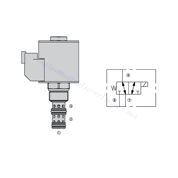
30SD10-34 Solenoid Directional Valve Parameter:
| Nominalus slėgis | 207 barai (3000 psi) | |
| Įrodymo slėgis | 350 bar (5075 psi) | |
| Didžiausias srautas | 22.7 L/min (6 gpm) | |
| Skystis | Mineraliniai arba sintetiniai, turintys tepimo savybių | |
| Temperature range ℃ | -54–107 ℃ (poliuretano sandarikliai) | |
| -40–100 ℃ (Buna N sandarikliai) | ||
| -26–204 ℃ (fluorokarboniniai sandarikliai) | ||
| Klampumo diapazonas | 7,4–420 mm2/s | |
| Užterštumo laipsnis | Minimalus taršos lygis yra ISO4406 20/18/14 lygis, o norint pailginti tarnavimo laiką, rekomenduojamas 17/15/13 lygis. | |
| Vidinis nuotėkis | ≤ 115 mL/min@207bar | |
| Ertmė | VC10-3 | |
| Ritės darbo įvertinimas | Nuolatinė vardinė įtampa nuo 85% iki 115% | |
| Response time | First indication of change of state with 100% voltage supplied at80% of nominal flow rating:Energized: 60 msec. ; De-energized: 10 msec. | |
| Pradinė ritės srovės trauka esant 20 ℃ | E-ritė | 1,7 A esant 12 V nuolatinės srovės įtampai; 0,85 A esant 24 V nuolatinės srovės įtampai |
| D-ritė | 1,67 A esant 12 V nuolatinės srovės įtampai; 0,83 A esant 24 V nuolatinės srovės įtampai | |
| Minimali įjungimo įtampa | 85% nominalios vertės esant 207 barų slėgiui | |
30SD10-34 Solenoid Directional Valve Advantages:
• Nuolatinio veikimo ritė
• Efektyvi šlapio armatūros konstrukcija
• Kasečių įtampa keičiama
• Papildomai įsigyjamos vandeniui atsparios elektroninės ritės, kurių apsaugos klasė siekia iki IP69K
• All ports may be fully pressurized
• Pramoninė bendroji ertmė
• Grūdintos dalys ilgam tarnavimo laikui ir mažam nuotėkiui
Usage Method Of 30SD10-34 Solenoid Directional Valve:
- Integration into System: Integrate the 30SD10-34 solenoid directional valve into the fluid control system following the manufacturer’s guidelines and specifications. Ensure proper alignment and connection between the valve and other system components to achieve optimal performance.
- Electrical Connection: Establish a secure electrical connection for the solenoid directional valve. Refer to the provided wiring diagram and ensure correct polarity to prevent any electrical malfunctions. Follow safety guidelines when working with electrical connections.
- Fluid Flow Direction Control: Utilize the solenoid directional valve to control the direction of fluid flow. The valve is typically equipped with a lever or actuator for manual adjustment. Alternatively, it can be integrated into an automated control system for remote operation.
- Pressure Adjustment: Employ the solenoid directional valve to regulate fluid pressure within the system. By adjusting the valve’s settings, you can achieve the desired pressure levels for optimal performance and efficiency.
How To Plumb Auto Cycle Hydraulic Valve?
Plumbing an auto-cycle hydraulic valve requires careful attention to ensure proper installation and functionality. Follow these steps to plumb an auto-cycle hydraulic valve effectively:
- Surinkite reikiamus įrankius ir medžiagas: Before you begin, make sure you have all the required tools and materials, including hydraulic hoses, fittings, adapters, Teflon tape, wrenches, and a hydraulic fluid reservoir.
- Identify The Valve Ports: Examine the auto-cycle hydraulic valve to identify the different ports. Typically, there will be inlet ports, outlet ports, and possibly additional ports for pressure relief or auxiliary functions.
- Determine The Hydraulic Fluid Flow Direction: Determine the desired flow direction of the hydraulic fluid through the valve. This information is crucial for correctly connecting the inlet and outlet ports.
- Install Fittings And Adapters: Install the appropriate fittings and adapters onto the valve ports. Ensure they are tightened securely, but be careful not to overtighten and damage the threads.
- Apply Teflon Tape: Wrap Teflon tape around the threads of the fittings and adapters. This helps create a tight seal and prevents leaks.
- Connect Hydraulic Hoses: Attach hydraulic hoses to the fittings and adapters on the valve ports. Ensure the hoses are suitable for the hydraulic system’s pressure rating and are of the correct length.
- Secure Hose Connections: Use hose clamps or other suitable methods to secure the hydraulic hoses to the fittings. This prevents the hoses from coming loose during operation.
- Route The Hydraulic hoses: Carefully route the hydraulic hoses to connect the auto-cycle hydraulic valve to the hydraulic fluid reservoir and other hydraulic components, such as cylinders or motors. Avoid sharp bends or kinks in the hoses that could restrict fluid flow.
- Check For Leaks: Once all connections are made, check for leaks. Start by slowly pressurizing the system and inspecting each connection point. If you notice any leaks, tighten the fittings or replace faulty components as necessary.
- Fill The Hydraulic Fluid Reservoir: Fill the hydraulic fluid reservoir with the recommended type and quantity of hydraulic fluid. Refer to the manufacturer’s guidelines for the appropriate fluid specifications.
- Bleed Air From The System: B bleed any air trapped in the hydraulic system to ensure proper operation. Follow the manufacturer’s instructions for bleeding procedures, which typically involve cycling the design and opening bleed valves.
- Test The System: With the plumbing complete, test the auto-cycle hydraulic valve and the overall system’s performance. Verify that the valve functions as intended and that fluid flow is smooth and consistent.
Gamyklos pajėgumai ir talpa:
(1) Surinkimas
Turime pirmos klasės nepriklausomą tyrimų ir plėtros surinkimo platformą. Hidraulinių cilindrų gamybos ceche yra keturios pusiau automatinės kėlimo cilindrų surinkimo linijos ir viena automatinė pakreipimo cilindrų surinkimo linija, kurių projektinis metinis gamybos pajėgumas yra 1 milijonas vienetų. Specialiųjų cilindrų ceche įrengta įvairių specifikacijų pusiau automatinė valymo surinkimo sistema, kurios projektinis metinis gamybos pajėgumas yra 200 000 vienetų, ir garsi CNC apdirbimo įranga, apdirbimo centras, didelio tikslumo cilindrų apdirbimo speciali įranga, robotinis suvirinimo aparatas, automatinis valymo aparatas, automatinis cilindrų surinkimo aparatas ir automatinė dažymo gamybos linija. Esama daugiau nei 300 rinkinių (komplektų) kritinė įranga. Optimalus įrangos išteklių paskirstymas ir efektyvus naudojimas užtikrina gaminių tikslumo reikalavimus ir aukštus gaminių kokybės poreikius.


(2) Apdirbimas
Mechaninio apdirbimo ceche įrengtas pritaikytas nuožulnaus bėgio tekinimo centras, apdirbimo centras, greitaeigis galandimo staklės, suvirinimo robotas ir kita susijusi įranga, galinti apdirbti cilindrinius vamzdžius, kurių maksimalus vidinis skersmuo yra 400 mm, o maksimalus ilgis – 6 metrai.

(3) Suvirinimas

(4) Dažymas ir dengimas
Su mažomis ir vidutinio dydžio cilindrinėmis automatinėmis vandens pagrindo dažų dengimo linijomis, siekiant automatinio robotų pakrovimo ir iškrovimo bei automatinio purškimo, projektinis pajėgumas yra 4000 vienetų per pamainą;
Taip pat turime pusiau automatinę didelių cilindrų dažų gamybos liniją, varomą grandinės, kurios projektinis našumas yra 60 dėžių per pamainą.


(5) Testavimas
Turime aukščiausios klasės patikros patalpas ir bandymų stendus, kad užtikrintume, jog baliono veikimas atitinka reikalavimus.

Esame vienas geriausių hidraulinių cilindrų gamintojų. Galime pasiūlyti išsamius hidraulinius cilindrus. Taip pat teikiame atitinkamus žemės ūkio pavarų dėžėsMes eksportuojame savo gaminius klientams visame pasaulyje ir pelnėme gerą reputaciją dėl aukščiausios gaminių kokybės ir aptarnavimo po pardavimo. Mes laukiame klientų šalyje ir užsienyje, norinčių susisiekti su mumis derėtis dėl verslo, keistis informacija ir... bendradarbiauti su mumis!