30SD10-40 Solenoid Directional Valve
30SD10-40 Solenoid Directional Valve
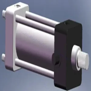
The 30SD10-40 solenoid directional valve is a high-performance industrial component designed to deliver precise and reliable fluid control in a variety of applications. With its advanced features, durable construction, and user-friendly design, this solenoid directional valve offers enhanced efficiency and operational reliability.
The 30SD10-40 solenoid directional valve is a reliable and versatile component that offers precise fluid control in industrial applications. Its robust construction, precision control, and reliable performance enhance efficiency and productivity in fluid control systems. By following the recommended usage methods and maintenance guidelines, you can ensure optimal performance and longevity of the 30SD10-40 solenoid directional valve in your industrial operations.
30SD10-40 Solenoid Directional Valve Characteristics:
- Robust Construction: The 30SD10-40 solenoid directional valve is built with exceptional craftsmanship and high-quality materials, ensuring durability and longevity. Its sturdy construction allows it to withstand demanding industrial environments, providing reliable performance even in harsh conditions.
- Versatile Functionality: This solenoid directional valve offers versatile functionality, making it suitable for a wide range of applications. It effectively controls the direction of fluid flow, enabling precise and efficient operation in various industrial systems.
- Precision Control: The 30SD10-40 solenoid directional valve provides exceptional precision in fluid control. It allows for accurate regulation and adjustment of fluid direction and pressure, ensuring optimal performance and efficiency in industrial processes.
- Reliable Performance: This solenoid directional valve delivers reliable performance, minimizing the risk of system failures or interruptions. It operates with dependability, contributing to increased productivity and reduced downtime in industrial operations.
30SD10-40 Solenoid Directional Valve Parameter:
| Nominalus slėgis | 207 barai (3000 psi) | |
| Didžiausias srautas | 23 L/min (6 gpm) | |
| Skystis | Mineraliniai arba sintetiniai, turintys tepimo savybių | |
| Temperature range ℃ | -54–107 ℃ (poliuretano sandarikliai) | |
| -40–100 ℃ (Buna N sandarikliai) | ||
| -26–204 ℃ (fluorokarboniniai sandarikliai) | ||
| Klampumo diapazonas | 7,4–420 mm2/s | |
| Užterštumo laipsnis | Minimalus taršos lygis yra ISO4406 20/18/14 lygis, o norint pailginti tarnavimo laiką, rekomenduojamas 17/15/13 lygis. | |
| Vidinis nuotėkis | ≤ 82 mL/min@207bar | |
| Ertmė | VC10-4 | |
| Ritės darbo įvertinimas | Nuolatinė vardinė įtampa nuo 85% iki 115% | |
| Pradinė ritės srovės trauka esant 20 ℃ | E-ritė | 1,7 A esant 12 V nuolatinės srovės įtampai; 0,85 A esant 24 V nuolatinės srovės įtampai |
| D-ritė | 1,67 A esant 12 V nuolatinės srovės įtampai; 0,83 A esant 24 V nuolatinės srovės įtampai | |
| Minimali įjungimo įtampa | 85% nominalios vertės esant 207 barų slėgiui | |
30SD10-40 Solenoid Directional Valve Advantages:
• Nuolatinio veikimo ritė
• Kasečių įtampa keičiama
• Papildomai įsigyjamos vandeniui atsparios elektroninės ritės, kurių apsaugos klasė siekia iki IP69K
• Efektyvi šlapio armatūros konstrukcija
• Pramoninė bendroji ertmė
• Grūdintos dalys ilgam tarnavimo laikui
Usage Method Of 30SD10-40 Solenoid Directional Valve :
- Integration into the System: Integrate the 30SD10-40 Solenoid Directional Valve into the fluid control system following the manufacturer’s guidelines and specifications. Ensure proper alignment and connection between the valve and other system components to achieve optimal performance.
- Electrical Connection: Establish a secure electrical connection for the solenoid directional valve. Follow the provided wiring diagram and ensure correct polarity to prevent electrical malfunctions. Adhere to safety guidelines when working with electrical connections.
- Fluid Flow Direction Control: Utilize the solenoid directional valve to control the direction of fluid flow. The valve is typically equipped with a lever or actuator for manual adjustment. Alternatively, it can be integrated into an automated control system for remote operation.
- Pressure Adjustment: Use the solenoid directional valve to regulate fluid pressure within the system. Adjust the valve’s settings to achieve the desired pressure levels for optimal performance and efficiency.
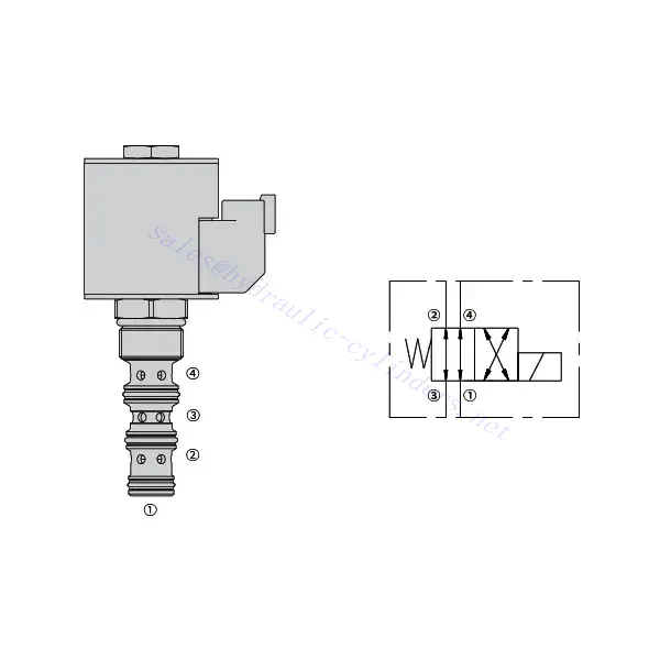
How To Read Hydraulic Valve Schematics?
Reading hydraulic valve schematics requires a basic understanding of hydraulic symbols and their meanings. Here are the steps to help you read hydraulic valve schematics:
- Familiarize Yourself With Hydraulic Symbols: Hydraulic schematics use graphical symbols to represent various components and functions. Common symbols include squares for valves, lines for pipes or hoses, arrows for flow direction, and circles for pressure or flow control devices. Make sure you understand the meaning of these symbols before proceeding.
- Identify The Valve Types: Look for the valve symbols in the schematic. Valves can be represented by squares with different shapes and orientations. For example, a square with a diagonal line represents a check valve, while a square with an arrow inside denotes a directional control valve.
- Determine The Valve Function: Each valve symbol indicates its specific function. Directional control valves determine the flow direction of hydraulic fluid, while pressure control valves regulate pressure levels. Flow control valves manage the rate of fluid flow, and check valves allow flow in one direction only.
- Observe The Valve Connections: Pay attention to the lines or arrows entering and exiting the valve symbol. These lines represent the hydraulic fluid flow paths. Arrows indicate the flow direction, and lines connecting valves and other components indicate the connections.
- Analyze The Valve Ositions: Some hydraulic valve schematics include symbols to illustrate the valve positions. These symbols typically depict the valve spool or lever in different positions, such as open, closed, or partially open. Understanding the valve positions helps you determine the flow paths and the state of the hydraulic system.
- Consider Additional Symbols And Annotations: Hydraulic schematics may include additional symbols and annotations to indicate pressure gauges, flow meters, filters, accumulators, or other components. Familiarize yourself with these symbols and their meanings to gain a comprehensive understanding of the system.
- Follow The Flow Paths: Trace the flow paths from the hydraulic power source through the various valves and components to the actuator or desired output. Understand how the valves interact with one another and how they control fluid flow, pressure, and direction to achieve the desired system operation.
- Refer To The Legend Or Key: The schematic should have a legend or key that explains the meaning of each symbol used in the diagram. If you encounter unfamiliar symbols or have doubts about their meaning, refer to the legend for clarification.
- Seek Additional Resources If Needed: If you need a more in-depth understanding of hydraulic valve schematics, consider referring to hydraulic textbooks, online resources, or consulting with hydraulic experts who can provide guidance and explanations tailored to your specific needs.
Gamyklos pajėgumai ir talpa:
(1) Surinkimas
Turime pirmos klasės nepriklausomą tyrimų ir plėtros surinkimo platformą. Hidraulinių cilindrų gamybos ceche yra keturios pusiau automatinės kėlimo cilindrų surinkimo linijos ir viena automatinė pakreipimo cilindrų surinkimo linija, kurių projektinis metinis gamybos pajėgumas yra 1 milijonas vienetų. Specialiųjų cilindrų ceche įrengta įvairių specifikacijų pusiau automatinė valymo surinkimo sistema, kurios projektinis metinis gamybos pajėgumas yra 200 000 vienetų, ir garsi CNC apdirbimo įranga, apdirbimo centras, didelio tikslumo cilindrų apdirbimo speciali įranga, robotinis suvirinimo aparatas, automatinis valymo aparatas, automatinis cilindrų surinkimo aparatas ir automatinė dažymo gamybos linija. Esama daugiau nei 300 rinkinių (komplektų) kritinė įranga. Optimalus įrangos išteklių paskirstymas ir efektyvus naudojimas užtikrina gaminių tikslumo reikalavimus ir aukštus gaminių kokybės poreikius.


(2) Apdirbimas
Mechaninio apdirbimo ceche įrengtas pritaikytas nuožulnaus bėgio tekinimo centras, apdirbimo centras, greitaeigis galandimo staklės, suvirinimo robotas ir kita susijusi įranga, galinti apdirbti cilindrinius vamzdžius, kurių maksimalus vidinis skersmuo yra 400 mm, o maksimalus ilgis – 6 metrai.

(3) Suvirinimas

(4) Dažymas ir dengimas
Su mažomis ir vidutinio dydžio cilindrinėmis automatinėmis vandens pagrindo dažų dengimo linijomis, siekiant automatinio robotų pakrovimo ir iškrovimo bei automatinio purškimo, projektinis pajėgumas yra 4000 vienetų per pamainą;
Taip pat turime pusiau automatinę didelių cilindrų dažų gamybos liniją, varomą grandinės, kurios projektinis našumas yra 60 dėžių per pamainą.


(5) Testavimas
Turime aukščiausios klasės patikros patalpas ir bandymų stendus, kad užtikrintume, jog baliono veikimas atitinka reikalavimus.

Esame vienas geriausių hidraulinių cilindrų gamintojų. Galime pasiūlyti išsamius hidraulinius cilindrus. Taip pat teikiame atitinkamus žemės ūkio pavarų dėžėsMes eksportuojame savo gaminius klientams visame pasaulyje ir pelnėme gerą reputaciją dėl aukščiausios gaminių kokybės ir aptarnavimo po pardavimo. Mes laukiame klientų šalyje ir užsienyje, norinčių susisiekti su mumis derėtis dėl verslo, keistis informacija ir... bendradarbiauti su mumis!