
4WRA(E) Series Direct operated Proportional Directional Hydraulic Valve
4WRA(E) Series Direct operated Proportional Directional Hydraulic Valve
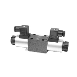
The 4WRA(E) series direct operated proportional directional hydraulic valve is a state-of-the-art hydraulic component designed to provide precise control and efficient operation in hydraulic systems. With its direct-operated proportional directional control technology, this valve offers accurate flow control, seamless direction changes, and optimized performance.
The 4WRA(E) series direct operated proportional directional hydraulic valve empowers hydraulic systems with precise flow control, versatile directional changes, and optimal energy efficiency. Its direct-operated proportional control technology ensures accurate and responsive operation, while the high flow capacity and energy-efficient design contribute to enhanced system performance. By following the recommended usage methods and maintenance guidelines, you can maximize the benefits and longevity of the 4WRA(E) series valve, elevating your hydraulic system to new levels of precision and efficiency. Upgrade your hydraulic setup today and experience the power of the 4WRA(E) series direct operated proportional directional hydraulic valve.
4WRA(E) Series Direct operated Proportional Directional Hydraulic Valve Key Characteristics:
- Direct Operated Proportional Control:
- The 4WRA(E) series valve utilizes direct-operated proportional control, allowing for precise and immediate response to control signals.
- This feature ensures accurate flow control and seamless transitions between different hydraulic functions.
- Augsta plūsmas jauda:
- With its robust design, the valve offers high flow capacity, making it suitable for applications requiring substantial hydraulic power.
- It allows for efficient handling of large fluid volumes, contributing to enhanced system performance.
- Versatile Directional Control:
- The 4WRA(E) series valve provides versatile directional control, enabling smooth and precise changes in hydraulic fluid direction.
- It allows for the seamless activation of hydraulic components such as cylinders, motors, and actuators in different directions.
- Energy Efficiency:
- Designed with energy efficiency in mind, this valve minimizes pressure drops and optimizes flow control, resulting in reduced energy consumption.
- By efficiently managing hydraulic power, it helps maximize system performance while minimizing operational costs.
4WRA(E) Series Direct operated Proportional Directional Hydraulic Valve Parameter:
| Hidrauliskā | ||||||||
| Uzstādīšanas pozīcija | optional, preferably horizontal | |||||||
| Izmērs | 6 | 10 | ||||||
| Svars | 4WRA…L2X | Kg | 2 | 6.6 | ||||
| 4WRAE…L2X | 2.2 | 6.8 | ||||||
| Rated flow qnom,when Δp = 10 bar | L/min | 7、15、26 | 30、60 | |||||
| Histerēze | % | ≤5 | ||||||
| Atkārtojamība | % | ≤1 | ||||||
| Response sensitivity | % | ≤0.5 | ||||||
| Maks. darba spiediens | Port s A B P | bārs | 315 | |||||
| Port T | bārs | 210 | ||||||
| Šķidrums | Minerāleļļa, kas piemērota NBR un FKM blīvējumiem | |||||||
| Fosfāta esteris FKM blīvējumam | ||||||||
| Šķidruma temperatūras diapazons | 4WRA…L2X | ℃ | -20℃ to 70℃(-4°F to 158°F) | |||||
| 4WRAE…L2X | ℃ | -20℃ to 50℃(-4° F to 122° F) | ||||||
| Viskozitātes diapazons | mm²/s | 20 to 380(preferably 30 to 46) | ||||||
| Piesārņojuma pakāpe | NAS1638 class9 or ISO 4406 class 20/18/15 | |||||||
| Elektriskie dati | ||||||||
| 1)solenoid | ||||||||
| Voltage type | Līdzstrāva | |||||||
| Command value signal | ±10V or 4~20mA | |||||||
| Max. current per solenoid | A | 2.5 | 1.5 | 0.8 | ||||
| Spoles pretestība | Cold value | Ω | 2 | 4.8 | 19.5 | |||
| Max. warm value | 3 | 7.2 | 28.8 | |||||
| Duty | % | ED100% | ||||||
| Coil temperature | ℃ | 150 | ||||||
| Valve protection to EN 60529 | IP65 | |||||||
| 2)Control electronics | ||||||||
| Ampilfier | 4WRA…L2X | VT-VSPA2-L2X | ||||||
| 4WRAE…L2X | Integrated in the valve(OBE) | |||||||
| Operating voltage | Nominal voltage | VDC | 24 | |||||
| Lower limiting value | V | 21/22(4WRA),19(4WRAE) | ||||||
| Upper limiting value | V | 35 | ||||||
| Amplifier current consumption | Imax | A | <1.8 | |||||
| Imax | A | 3 | ||||||
4WRA(E) Series Direct operated Proportional Directional Hydraulic Valve Advantages:
• Direct-acting proportional directional valve, used to control the flow and direction of liquid flow
• Panel type installation
• The proportional solenoid actuates the valve core through the threaded connection, and the coil can be removed separately
• Spool spring alignment alignment
• Optional with built-in amplifier, 4WRAE…L2X type input can be A1 or F1
• Supporting supply of external amplifier
Usage Method Of 4WRA(E) Series Direct operated Proportional Directional Hydraulic Valve:
- Sistēmas novērtēšana:
- Evaluate your hydraulic system and identify the specific flow control and directional requirements.
- Determine if the 4WRA(E) series valve is suitable based on its flow capacity, pressure rating, and compatibility with your system.
- Vārsta izvēle:
- Select the appropriate variant of the 4WRA(E) series valve based on your system parameters, flow requirements, and directional control needs.
- Ņemiet vērā tādus faktorus kā maksimālais plūsmas ātrums, spiediena vērtējums, reakcijas laiks un ekspluatācijas apstākļi.
- Uzstādīšana:
- Rūpīgi ievērojiet ražotāja uzstādīšanas instrukcijas, nodrošinot pareizu izlīdzināšanu un drošu vārsta stiprinājumu.
- Pievienojiet vārstu hidrauliskajai sistēmai, nodrošinot savienojumus bez noplūdēm un pareizu plūsmas virziena izlīdzināšanu.
- Vadības signāla savienojums:
- Connect the control signal wires of the valve to the appropriate control device, such as a proportional amplifier or electronic control unit.
- Ensure proper wiring and compatibility between the valve and the control device to enable accurate and responsive control.
How To Adjust Valve Lash On Hydraulic Lifters?
Adjusting valve lash on hydraulic lifters is a crucial maintenance task to ensure proper engine performance and prevent issues such as noisy valves or reduced power. Here’s a step-by-step guide on how to adjust valve lash on hydraulic lifters:
- Sagatavošana:
- Ensure the engine is off and cool before starting the adjustment process.
- Familiarize yourself with the engine’s firing order and the specific valve lash specifications provided by the manufacturer for your engine model.
- Identify the Correct Cylinder:
- Locate the firing position of the engine by referring to the engine’s firing order diagram.
- Identify the cylinder that corresponds to the specific valve you want to adjust.
- Novietojiet cilindru:
- Rotate the engine crankshaft manually using a socket wrench or the engine’s built-in turning mechanism.
- Position the cylinder you want to adjust at the top dead center (TDC) on the compression stroke. You can do this by aligning the timing marks on the crankshaft pulley or using a piston stop tool.
- Loosen the Rocker Arm:
- Locate the rocker arm on the specific valve you want to adjust.
- Loosen the rocker arm nut or adjuster screw using an appropriate wrench or socket.
- Adjust the Valve Lash:
- With the rocker arm loose, you can now adjust the valve lash. The valve lash is the clearance between the rocker arm and the valve stem.
- Use a feeler gauge to measure the existing valve lash. Insert the appropriate thickness gauge between the rocker arm and the valve stem.
- If the clearance is too tight, meaning the feeler gauge does not fit or has excessive resistance, you need to increase the valve lash. If the clearance is too loose, meaning the feeler gauge slides in too easily, you need to decrease the valve lash.
- To adjust the valve lash, tighten or loosen the rocker arm nut or adjuster screw accordingly. Refer to the manufacturer’s specifications for the recommended amount of adjustment to be made.
- Recheck the Valve Lash:
- After making the adjustment, recheck the valve lash using the feeler gauge to ensure it falls within the recommended specifications.
- Repeat the adjustment process if necessary until the correct valve lash is achieved.
- Repeat for Other Cylinders:
- Proceed to the next cylinder in the firing order and repeat steps 4 to 6 for each cylinder you want to adjust.
- Remember to rotate the crankshaft and position each cylinder at TDC on the compression stroke before adjusting its valve lash.
- Secure the Rocker Arm:
- Once the valve lash is properly adjusted for each cylinder, tighten the rocker arm nut or adjuster screw to the manufacturer’s recommended torque specification.
- Double-check that the valve lash remains within the specified range after tightening.
- Noslēguma pārbaudes:
- Rotate the engine crankshaft a few times to ensure smooth rotation and check for any unusual noises or resistance.
- Start the engine and listen for any abnormal valve noises. If you hear excessive tapping or knocking, recheck the valve lash adjustment.
Rūpnīcas iespējas un jauda:
(1) Montāža
Mums ir pirmklasīga neatkarīga pētniecības un attīstības montāžas platforma. Hidraulisko cilindru ražošanas darbnīcā ir četras pusautomātiskas pacelšanas cilindru montāžas līnijas un viena automātiskā slīpuma cilindru montāžas līnija ar projektēto gada ražošanas jaudu 1 miljons vienību. Speciālo cilindru darbnīca ir aprīkota ar dažādu specifikāciju pusautomātisku tīrīšanas montāžas sistēmu ar projektēto gada ražošanas jaudu 200 000 vienību un aprīkota ar slavenām CNC apstrādes iekārtām, apstrādes centru, augstas precizitātes cilindru apstrādes speciālo aprīkojumu, robotizētu metināšanas iekārtu, automātisku tīrīšanas iekārtu, automātisku cilindru montāžas iekārtu un automātisku krāsošanas ražošanas līniju. Esošais kritiskais aprīkojums ir vairāk nekā 300 komplektu (komplektu). Optimāla iekārtu resursu sadale un efektīva izmantošana nodrošina produktu precizitātes prasības un apmierina produktu augstās kvalitātes prasības.


(2) Apstrāde
Apstrādes cehs ir aprīkots ar pielāgotu slīpo sliežu virpošanas centru, apstrādes centru, ātrgaitas asināšanas mašīnu, metināšanas robotu un citu saistītu aprīkojumu, kas var apstrādāt cilindriskas caurules ar maksimālo iekšējo diametru 400 mm un maksimālo garumu 6 metri.

(3) Metināšana

(4) Krāsošana un pārklāšana
Ar mazām un vidēja izmēra cilindriskām automātiskām ūdens bāzes krāsu pārklāšanas līnijām, lai panāktu automātisku robotu iekraušanu un izkraušanu un automātisku izsmidzināšanu, projektētā jauda ir 4000 gabali maiņā;
Mums ir arī pusautomātiska krāsu ražošanas līnija lieliem baloniem, ko darbina ķēdes piedziņa, ar 60 kastu konstrukcijas jaudu vienā maiņā.


(5) Testēšana
Mums ir augstākās klases pārbaudes iekārtas un testēšanas stendi, lai nodrošinātu, ka balona veiktspēja atbilst prasībām.

Mēs esam viens no labākajiem hidraulisko cilindru ražotājiem. Mēs varam piedāvāt visaptverošus hidrauliskos cilindrus. Mēs nodrošinām arī atbilstošus lauksaimniecības pārnesumkārbas. Mēs esam eksportējuši savus produktus klientiem visā pasaulē un esam ieguvuši labu reputāciju, pateicoties mūsu izcilajai produktu kvalitātei un pēcpārdošanas servisam. Mēs aicinām klientus no valsts un ārvalstīm sazināties ar mums, lai risinātu biznesa sarunas, apmainītos ar informāciju un... sadarboties ar mums!


