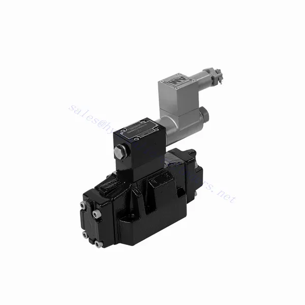
GWEH Series Explosion-proof Directional Hydraulic Valve
GWEH Series Explosion-proof Directional Hydraulic Valve
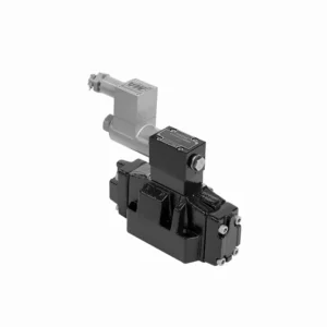
The GWEH series explosion-proof directional hydraulic valve is an innovative solution designed to provide optimal safety and precise control in hydraulic systems operating in hazardous environments. With its explosion-proof features, reliable performance, and advanced functionalities, this valve offers enhanced safety measures, efficient fluid flow control, and compatibility with various industrial applications.
The GWEH series explosion-proof directional hydraulic valve is a reliable and efficient solution for industries operating in hazardous environments. With its explosion-proof design, precise directional control, versatility, and high performance, this valve ensures safety and control in hydraulic systems. Following the recommended usage methods and adhering to regular maintenance practices, the GWEH series valve delivers safe and efficient operation in explosive atmospheres. Upgrade your hydraulic system with the GWEH series explosion-proof directional hydraulic valve and experience enhanced safety, optimal fluid flow control, and reliable performance.
GWEH Series Explosion-proof Directional Hydraulic Valve Key Characteristics:
- Explosion-proof Design:
- The GWEH series valve is engineered with a robust explosion-proof design, ensuring safe operation in environments containing flammable gases or dust.
- It complies with stringent safety standards and certifications, minimizing the risk of ignition and ensuring the safety of personnel and equipment.
- Virziena vadība:
- This hydraulic valve provides precise directional control of fluid flow, allowing for the activation and deactivation of specific hydraulic actuators.
- It enables smooth and reliable operation of various hydraulic functions, such as cylinder extension and retraction or motor direction changes.
- Versatility and Compatibility:
- The GWEH series valve is highly versatile and compatible with various hydraulic systems and applications.
- It can seamlessly integrate into industrial machinery, mobile equipment, and automation systems operating in hazardous environments.
- Augsta veiktspēja:
- With its advanced design and high-quality construction, the GWEH series hydraulic valve delivers exceptional performance and reliability.
- It ensures consistent and precise control over fluid flow, contributing to efficient and optimized system operation.
GWEH Series Explosion-proof Directional Hydraulic Valve Parameter:
NG10
| Working pressureP,A,B | bārs | 315 | |||||||||
| Port T | With external pilot oil drain | bārs | 315 | ||||||||
| With internal pilot oil drain | bārs | 210 | |||||||||
| Y osta | With external pilot oil drain | bārs | 210 | ||||||||
| Min. control pressure | With external pilot oil supply
With internal pilot oil supply (not apply to C, Z, F, G, H, P, T, V) |
bārs | 3-position valve 10 | ||||||||
| Spring-return 2-position valve 10 | |||||||||||
| Hydraulic-return 2-position valve 7 | |||||||||||
| With internal pilot oil supply ( apply to C, Z, F, G, H, P, T, V) |
bārs | 4.5 | |||||||||
| Max. control pressure | bārs | 250 | |||||||||
| Šķidrums | Mineral oil,Phosphate ester | ||||||||||
| Šķidruma temperatūras diapazons | ℃ | -30 to +80 ( NBR seals | |||||||||
| -20 to +80 ( FKM seals ) | |||||||||||
| Viskozitātes diapazons | mm2/s | 2,8 līdz 500 | |||||||||
| Controlled quantity in commutating process | cm3 | 3-position valve 2.04 2-position valve 4.08 | |||||||||
| Switching times (= Valve switching time from the neutral position to the switched position)(DC ) | |||||||||||
| Control pressure | bārs | 70 | 140 | 210 | 250 | ||||||
| 3-position valve | kundze | 65 | 60 | 55 | 50 | ||||||
| 2-position valve | kundze | 80 | 75 | 70 | 65 | ||||||
| Switching times (= Valve switching time from the switched position to the neutral position) | |||||||||||
| 3-position valve | kundze | 30 | |||||||||
| 2-position valve | kundze | 35 | 40 | 30 | 35 | 25 | 30 | 20 | 25 | ||
| Flow of shortest switching time | L/min | about 35 | |||||||||
| Uzstādīšanas pozīcija | HC, HD, HK, HZ and HY of hydraulic return shall be installed horizontally. The rest are arbitrary | ||||||||||
NG16
| Specifikācijas | G-..WEH16../6B2.. type | |||||||
| Working pressureP,A,B bar | 350 | |||||||
| Port T | With external pilot oil drain bar | 250 | ||||||
| With internal pilot oil drain bar | 210 | |||||||
| Hydraulic-centering 3-position valve With internal pilot oil drain is impossible | ||||||||
| Y osta | With external pilot oil drain bar | 210 | ||||||
| Min. control pressure | With external pilot oil supply bar
With internal pilot oil supply bar |
3-position valve 14 | ||||||
| Spring-return 2-position valve 14 | ||||||||
| Hydraulic-return 2-position valve 14 | ||||||||
| With internal pilot oil supply ( apply to C、Z、F、G、H、P、T、V) bar |
When applying back pressure valve or the flow is large, enginery of spool valve is 4.5 bar as C、Z、F、G、H、P、T and V | |||||||
| Max. control pressure bar | 250 | |||||||
| Šķidrums | Mineral oil,Phosphate ester | |||||||
| Fluid temperature range ℃ | -30 to +80 ( NBR seals | |||||||
| -20 to +80 ( FKM seals ) | ||||||||
| Viscosity range mm2 /s 2 | 2.8 to 500 | |||||||
| Switching pilot oil volume | ||||||||
| -Spring-centering 3-position valve cm3 | 5.72 | |||||||
| -2-position valve cm3 | 11.45 | |||||||
| * Switching times (= Valve switching time from the neutral position to the switched position)(AC and DC) | ||||||||
| Control pressure bar | 50 | 150 | 250 | |||||
| – Spring-centering 3-position valve ms | 65 | 60 | 58 | |||||
| – 2-position valve ms | 65 | 55 | 50 | |||||
| *Switching times (= Valve switching time from the neutral position to the switched position) | ||||||||
| – Spring-centering 3-position valve ms | 40 | |||||||
| – 2-position valve ms | 45 | 35 | 30 | |||||
| Uzstādīšanas pozīcija | C,D,K,Z,Y Type hydraulic-return valves are installed horizontally, the rest can be installed arbitrarily。 | |||||||
| Flow of shorter switching time L/min | about 35 | |||||||
| Weight of the valve kg | about 10.6 | |||||||
NG25
| Specifikācijas | G-H-…WEH25../6B2… type | |||||||||
| Working pressureP,A,B bar | 350 | |||||||||
| Port T | With external pilot oil drain bar | 250 | ||||||||
| With internal pilot oil drain bar | 210 | |||||||||
| Hydraulic-centering 3-position valve With internal pilot oil drain is impossible | ||||||||||
| Y osta | With external pilot oil drain bar | 210 | ||||||||
| Min. control pressure | With external pilot oil supply bar
With internal pilot oil supply bar |
Spring-centering 3-position valve 13 | ||||||||
| Hydraulic-centering 3-position valve 18 | ||||||||||
| Spring-return 2-position valve 13 | ||||||||||
| Hydraulic-return 2-position valve 18 | ||||||||||
| With internal pilot oil supply | When applying back pressure valve or the flow is large, enginery of spool valve is 4.5 bar as C、Z、F、G、H、P、T and V | |||||||||
| Max. control pressure bar | 250 | |||||||||
| Šķidrums | Mineral oil,Phosphate ester | |||||||||
| Fluid temperature range ℃ | -30 to +80 ( NBR seals | |||||||||
| -20 to +80 ( FKM seals ) | ||||||||||
| Viscosity range mm2 /s 2 | 2.8 to 500 | |||||||||
| Switching pilot oil volume | ||||||||||
| -Spring-centering 3-position valve cm3 | 14.2 | |||||||||
| -2-position valve cm3 | 28.4 | |||||||||
| * Switching times (= Valve switching time from the neutral position to the switched position)(AC and DC) | ||||||||||
| Control pressure bar | 50 | 140 | 210 | 250 | ||||||
| – Spring-centering 3-position valve ms | 85 | 75 | 70 | 65 | ||||||
| – 2-position valve ms | 160 | 130 | 120 | 105 | ||||||
| **Switching times (= Valve switching time from the neutral position to the switched position) | ||||||||||
| – Spring-centering 3-position valve ms | 40 | |||||||||
| – 2-position valve ms | 125 | 100 | 90 | 80 | ||||||
| Uzstādīšanas pozīcija | C,D,K,Z,Y Type hydraulic-return valves are installed horizontally, the rest can be installed arbitrarily。 | |||||||||
| Flow of shorter switching time L/min | about 35 | |||||||||
| Weight of the valve kg | about 19 | |||||||||
GWEH Series Explosion-proof Directional Hydraulic Valve Advantages:
• Directional valve directional the oil path by controlling the main spool
• WEH electrohydraulic control
• Two-position four-way or three-position four-way
• Installation face follows DIN 24340 A, ISO 4401, and CETOP-RP 121H Sub-plate mounting connection
• Nomainiet spoli, neizlaižot eļļu
Usage Method Of GWEH Series Explosion-proof Directional Hydraulic Valve :
- Hazardous Area Assessment:
- Conduct a thorough assessment of the hazardous area to identify the specific explosion-proof requirements and classification.
- Determine the appropriate safety measures and precautions needed to comply with the regulations.
- Vārsta izvēle:
- Select the GWEH Series Valve with the suitable specifications, considering factors such as pressure ratings, flow capacity, and voltage requirements.
- Ensure compatibility with the hydraulic system and the specific hazardous environment.
- Uzstādīšana:
- Follow the manufacturer’s instructions for proper installation of the GWEH Series Valve in the hydraulic system.
- Ensure secure mounting and proper electrical connections, adhering to the recommended torque values and wiring guidelines.
- Control and Activation:
- Utilize the recommended control method, such as electrical signals or remote activation, to operate the GWEH Series Valve.
- Connect the valve to a suitable power source and control system, following the provided wiring diagrams.
How Does A Hydraulic Control Valve Work?
A hydraulic control valve is a critical component in hydraulic systems that regulates the flow and direction of hydraulic fluid to control the operation of hydraulic actuators. It enables precise control over various hydraulic functions, such as extending or retracting cylinders, controlling motor speed and direction, or adjusting the flow rate of hydraulic fluid. Here’s an overview of how a hydraulic control valve works:
- Vārsta struktūra:
- A hydraulic control valve typically consists of a valve body, spools or poppets, and various internal passages.
- The valve body contains inlet and outlet ports for fluid connection and chambers that direct the flow.
- The spools or poppets are movable elements within the valve body that control the flow paths and connect the appropriate ports.
- Flow Control:
- The hydraulic control valve regulates the flow of hydraulic fluid by opening and closing specific flow paths within the valve.
- The position of the spools or poppets determines which ports are connected and allows fluid to flow in the desired direction.
- Virziena vadība:
- Hydraulic control valves provide directional control by selectively connecting or blocking fluid flow to different hydraulic actuators.
- By adjusting the position of the spools or poppets, the valve determines which actuator receives fluid and in which direction it moves.
- Actuation Methods:
- Hydraulic control valves can be actuated using manual levers, mechanical linkages, solenoids, or pilot pressure control.
- Manual control valves are operated by moving the levers or handles to position the spools or poppets.
- Solenoid-controlled valves use electromagnetic coils to actuate the valve, allowing for remote or automated control.
- Control Modes:
- Hydraulic control valves offer different control modes, such as 2-way, 3-way, or 4-way control.
- A 2-way control valve controls flow in one direction, allowing or blocking fluid flow.
- A 3-way control valve has three ports and can control the flow between two ports while blocking the third.
- A 4-way control valve has four ports and can route fluid between two actuator ports while blocking the other two.
- Spiediena kompensācija:
- Some hydraulic control valves are equipped with pressure compensation features to maintain a consistent flow rate despite changes in system pressure.
- These valves adjust the flow passages based on pressure differentials, allowing for precise control regardless of varying operating conditions.
- Feedback and Control Loops:
- Advanced hydraulic control valves may incorporate feedback mechanisms, such as position or pressure sensors, to provide feedback to a control system.
- This feedback enables closed-loop control, where the system can monitor and adjust the valve’s position or flow based on desired setpoints or operating conditions.
Rūpnīcas iespējas un jauda:
(1) Montāža
Mums ir pirmklasīga neatkarīga pētniecības un attīstības montāžas platforma. Hidraulisko cilindru ražošanas darbnīcā ir četras pusautomātiskas pacelšanas cilindru montāžas līnijas un viena automātiskā slīpuma cilindru montāžas līnija ar projektēto gada ražošanas jaudu 1 miljons vienību. Speciālo cilindru darbnīca ir aprīkota ar dažādu specifikāciju pusautomātisku tīrīšanas montāžas sistēmu ar projektēto gada ražošanas jaudu 200 000 vienību un aprīkota ar slavenām CNC apstrādes iekārtām, apstrādes centru, augstas precizitātes cilindru apstrādes speciālo aprīkojumu, robotizētu metināšanas iekārtu, automātisku tīrīšanas iekārtu, automātisku cilindru montāžas iekārtu un automātisku krāsošanas ražošanas līniju. Esošais kritiskais aprīkojums ir vairāk nekā 300 komplektu (komplektu). Optimāla iekārtu resursu sadale un efektīva izmantošana nodrošina produktu precizitātes prasības un apmierina produktu augstās kvalitātes prasības.


(2) Apstrāde
Apstrādes cehs ir aprīkots ar pielāgotu slīpo sliežu virpošanas centru, apstrādes centru, ātrgaitas asināšanas mašīnu, metināšanas robotu un citu saistītu aprīkojumu, kas var apstrādāt cilindriskas caurules ar maksimālo iekšējo diametru 400 mm un maksimālo garumu 6 metri.

(3) Metināšana

(4) Krāsošana un pārklāšana
Ar mazām un vidēja izmēra cilindriskām automātiskām ūdens bāzes krāsu pārklāšanas līnijām, lai panāktu automātisku robotu iekraušanu un izkraušanu un automātisku izsmidzināšanu, projektētā jauda ir 4000 gabali maiņā;
Mums ir arī pusautomātiska krāsu ražošanas līnija lieliem baloniem, ko darbina ķēdes piedziņa, ar 60 kastu konstrukcijas jaudu vienā maiņā.


(5) Testēšana
Mums ir augstākās klases pārbaudes iekārtas un testēšanas stendi, lai nodrošinātu, ka balona veiktspēja atbilst prasībām.

Mēs esam viens no labākajiem hidraulisko cilindru ražotājiem. Mēs varam piedāvāt visaptverošus hidrauliskos cilindrus. Mēs nodrošinām arī atbilstošus lauksaimniecības pārnesumkārbas. Mēs esam eksportējuši savus produktus klientiem visā pasaulē un esam ieguvuši labu reputāciju, pateicoties mūsu izcilajai produktu kvalitātei un pēcpārdošanas servisam. Mēs aicinām klientus no valsts un ārvalstīm sazināties ar mums, lai risinātu biznesa sarunas, apmainītos ar informāciju un... sadarboties ar mums!


