30SD38-38 Solenoïde richtingsventiel
30SD38-38 Solenoïde richtingsventiel
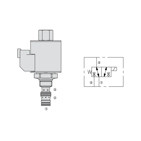
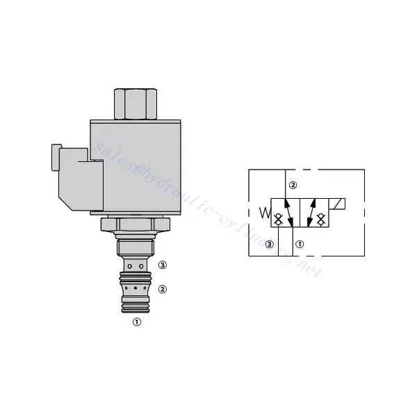
The 30SD38-38 solenoid directional valve is a highly efficient and versatile component that plays a pivotal role in fluid control systems. This valve is designed to deliver precise and reliable fluid control and offers exceptional performance and durability.
The 30SD38-38 solenoid directional valve is a reliable and efficient fluid control solution for various industrial applications. With its robust construction, efficient performance, and versatile mounting options, this valve provides precise control over fluid flow and enhances overall system performance. By following proper usage methods and implementing regular maintenance practices, you can ensure optimal functionality and longevity of the 30SD38-38 solenoid directional valve, making it an excellent choice for your fluid control needs.
30SD38-38 Solenoid Directional Valve Characteristics:
- Robust Construction: The 30SD38-38 solenoid directional valve is constructed with high-quality materials, ensuring durability and resistance to wear and corrosion. Its rugged design allows it to withstand harsh operating conditions, making it suitable for various industrial applications.
- Efficient Performance: Powered by a solenoid, this valve provides rapid response times, enabling quick adjustments to fluid flow and pressure. The efficient operation ensures precise control and seamless integration into automated processes.
- Versatile Mounting Options: The valve offers flexible mounting options, including inline, manifold, or subplate configuration. This versatility allows for easy installation and integration into various fluid control systems, accommodating different application requirements.
30SD38-38 Solenoid Directional Valve Parameter:
| Nominale druk | 207 bar (3000 psi) | |
| Piekstroom | Zie prestatiegrafiek | |
| Interne lekkage | ≤5 drops/min@207bar | |
| Spoelbelastingsclassificatie | Continu van 85% tot 115% van nominale spanning | |
| Initiële spoelstroomopname bij 20℃ | E-spoel | 1,7 A bij 12 VDC; 0,85 A bij 24 VDC |
| D-spoel | 1,67 A bij 12 VDC; 0,83 A bij 24 VDC | |
| Minimale intrekspanning | 85% van nominaal bij 207 bar (3000 psi) | |
| Holte | VC08-3 | |
| Vloeistof | Op mineralen gebaseerde of synthetische materialen met smerende eigenschappen | |
| Vloeistoftemperatuurbereik ℃ | -54 tot 107 ℃ (Polyurethaan afdichtingen) | |
| -40 tot 100 ℃ (Buna N-zeehonden) | ||
| -26 tot 204 ℃ (Fluorkoolstofafdichtingen) | ||
| Viscositeitsbereik | 7,4 tot 420 mm2/S | |
| Mate van verontreiniging | Het minimale vervuilingsniveau is ISO4406-niveau 20/18/14, en niveau 17/15/13 wordt aanbevolen om de levensduur te verlengen | |
30SD38-38 Solenoid Directional Valve Advantages:
• Spoel met continue belasting
• Cartridges zijn spanningsverwisselbaar
• Optionele waterdichte E-Coils met een IP69K-classificatie
• Efficiënte natte-ankerconstructie
• Algemene holte in de industrie
• Geharde onderdelen voor een lange levensduur
Usage Method Of 30SD38-38 Solenoid Directional Valve:
- Determine the application requirements: Identify the specific fluid control needs of your system. Consider factors such as flow rate, pressure, and direction to select the appropriate valve configuration.
- Mount the valve: Choose the suitable mounting option based on your system’s layout and available space. Ensure that the valve is securely positioned and aligned with the fluid lines.
- Connect the fluid lines: Use compatible fittings and connectors to establish the necessary connections between the valve and the fluid lines. Ensure tight and leak-free connections.
- Electrical connection: Connect the solenoid valve to the appropriate power source following the manufacturer’s instructions. Ensure proper wiring and observe safety precautions.
- Test and adjust: Once the valve is installed and connected, gradually introduce fluid flow and monitor its behavior. Test different operating conditions and adjust the valve settings as needed to achieve the desired fluid control.
How To Replace A Shower Mixing Valve Cartridge?
Replacing a shower mixing valve cartridge is a common DIY task that can help restore proper water temperature and flow control. Here’s a step-by-step guide on how to replace a shower mixing valve cartridge:
- Gather the necessary tools: Before starting the replacement process, gather the following tools: adjustable wrench, Phillips screwdriver, flathead screwdriver, pliers, Allen wrench (if applicable), and a replacement cartridge specific to your shower valve model.
- Turn off the water supply: Locate the main water shut-off valve for your home and turn it off to stop the water flow to the shower. If there isn’t a dedicated shut-off valve for the shower, you may need to shut off the main water supply.
- Remove the handle and trim: Start by removing the handle. Depending on the type of handle, you may need to locate a set screw or a decorative cap covering the screw. Use a flathead or Phillips screwdriver to remove the screw or pry off the cap, allowing you to detach the handle. Next, remove any trim or decorative coverings around the valve by gently pulling or unscrewing them.
- Access the cartridge: Depending on the valve design, you may need to remove additional components to access the cartridge. This can include a retaining nut, sleeve, or escutcheon plate. Use the appropriate tools to remove these components and expose the cartridge.
- Remove the old cartridge: Once you have clear access to the cartridge, use pliers or a specialized cartridge removal tool, if provided, to carefully pull out the old cartridge. Wiggle it back and forth if necessary. Be cautious not to damage any surrounding plumbing connections.
- Clean the valve body: Before installing the new cartridge, clean the valve body thoroughly to remove any debris or mineral buildup. Wipe it with a clean cloth or use a mild cleaning solution if needed.
- Install the new cartridge: Take the replacement cartridge and align it with the valve body, ensuring that any tabs or notches match up correctly. Push the cartridge firmly into place until it sits flush with the valve body.
- Reassemble the valve: Put back any components you removed earlier, such as the retaining nut, sleeve, or escutcheon plate. Make sure they are tightened securely but avoid overtightening.
- Test for leaks: Turn on the water supply and carefully observe the valve for any leaks. If you notice any leaks, tighten the connections or adjust the cartridge as needed. Check both the hot and cold water settings to ensure proper temperature control.
- Reinstall the trim and handle: Once you’ve confirmed that there are no leaks, reinstall the trim or decorative coverings over the valve. Slide the handle back onto the cartridge stem and secure it with the set screw or by replacing the decorative cap.
- Restore water supply: Finally, turn on the main water supply or the dedicated shut-off valve for the shower and test the functionality of the new cartridge. Verify that the water temperature and flow can be adjusted smoothly.
Vermogen en capaciteit van de fabriek:
(1) Montage
We beschikken over een eersteklas, onafhankelijk R&D-platform voor assemblage. De productiewerkplaats voor hydraulische cilinders beschikt over vier semi-automatische hefcilinderassemblagelijnen en één automatische kantelcilinderassemblagelijn, met een geplande jaarlijkse productiecapaciteit van 1 miljoen stuks. De speciale cilinderwerkplaats is uitgerust met diverse specificaties van een semi-automatisch reinigingsassemblagesysteem met een geplande jaarlijkse productiecapaciteit van 200.000 stuks en is uitgerust met gerenommeerde CNC-bewerkingsapparatuur, een bewerkingscentrum, een zeer nauwkeurige cilinderbewerkingsapparatuur, een robotlasmachine, een automatische reinigingsmachine, een automatische cilinderassemblagemachine en een automatische verfproductielijn. De bestaande kritische apparatuur bestaat uit meer dan 300 sets. De optimale toewijzing en het efficiënte gebruik van apparatuur garanderen de nauwkeurigheidseisen van producten en voldoen aan de hoge kwaliteitseisen.


(2) Bewerking
De bewerkingsruimte is uitgerust met een op maat gemaakt schuin rails draaicentrum, bewerkingscentrum, hogesnelheids hoonmachine, lasrobot en andere bijbehorende apparatuur, die de bewerking van cilinderbuizen met een maximale binnendiameter van 400 mm en een maximale lengte van 6 meter aankan.

(3) Lassen

(4) Schilderen en coaten
Met kleine en middelgrote automatische cilindercoatinglijnen voor watergedragen verf, om automatisch laden en lossen door robots en automatisch spuiten te bereiken, is de ontwerpcapaciteit 4000 stuks per ploegendienst;
Ook beschikken wij over een semi-automatische verfproductielijn voor grote cilinders, aangedreven door een kabelrups, met een ontwerpcapaciteit van 60 dozen per ploeg.


(5) Testen
Wij beschikken over eersteklas inspectiefaciliteiten en testbanken om te garanderen dat de prestaties van de cilinder aan de eisen voldoen.

Wij zijn een van de beste fabrikanten van hydraulische cilinders. We bieden een compleet assortiment hydraulische cilinders. Ook leveren we bijbehorende onderdelen. landbouwversnellingsbakkenWe hebben onze producten wereldwijd geëxporteerd en een goede reputatie opgebouwd dankzij onze superieure productkwaliteit en aftersalesservice. We nodigen klanten in binnen- en buitenland uit om contact met ons op te nemen om zaken te doen, informatie uit te wisselen en werk met ons samen!


