
4WRPEH Series Proportional Directional Hydraulic Valve
4WRPEH Series Proportional Directional Hydraulic Valve
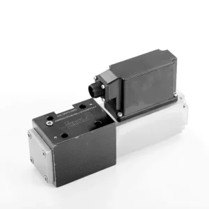
The 4WRPEH series proportional directional hydraulic valve is an advanced hydraulic component designed to deliver exceptional precision and control in hydraulic systems. With its innovative proportional directional control technology, this valve enables accurate flow regulation and smooth directional changes.
The 4WRPEH series proportional directional hydraulic valve empowers hydraulic systems with precise flow control, versatile functionality, and enhanced efficiency. Its proportional directional control technology ensures accurate and responsive flow adjustment, while the high flow capacity guarantees reliable performance even in demanding applications. By following the recommended usage methods and maintenance guidelines, you can maximize the benefits and longevity of the 4WRPEH series valve, elevating your hydraulic system to new levels of precision and control. Upgrade your hydraulic setup today and experience the power of the 4WRPEH series proportional directional hydraulic valve.
4WRPEH Series Proportional Directional Hydraulic Valve Key Characteristics:
- Proportionele richtingsregeling:
- The 4WRPEH series valve utilizes state-of-the-art proportional directional control technology, allowing precise and proportional flow adjustment based on control signals.
- This feature ensures accurate and responsive control, resulting in improved system performance, reduced energy consumption, and enhanced productivity.
- Veelzijdige functionaliteit:
- This valve offers versatile control over hydraulic fluid direction, making it suitable for a wide range of applications.
- It enables seamless activation and deactivation of hydraulic components such as cylinders, motors, and actuators in different directions, enhancing system flexibility and adaptability.
- Hoge stroomcapaciteit:
- The 4WRPEH series valve is engineered to handle high flow rates, making it ideal for applications that require substantial hydraulic power.
- Its robust construction ensures reliable performance even under demanding conditions, providing consistent and efficient flow control.
- Precise Metering:
- With its proportional control technology, this valve offers precise metering of hydraulic fluid, allowing for accurate control and regulation of flow rates.
- This precision enhances overall system performance and ensures precise movements of hydraulic actuators.
4WRPEH Series Proportional Directional Hydraulic Valve Parameter:
NG6
| Algemeen | |||||||
| Ontwerp | Spoelventiel, direct bediend, met stalen huls | ||||||
| Aandrijving | Proportionele solenoïde met positieregeling, OBE | ||||||
| Verbindingstype | Onderplaatmontage, poortpatroon volgens ISO 4401-03-02-0-05 | ||||||
| Installatiepositie | Elk | ||||||
| Omgevingstemperatuurbereik | ℃ | -20…+50 | |||||
| Gewicht | kg | ongeveer 2,75 | |||||
| Maximale trillingsbestendigheid (testconditie) | Max. 25 g, ruimtevibratietest in alle richtingen (24 uur) | ||||||
| Hydraulisch (gemeten bij p=100bar, met HLP46 bij ϑoil = 40℃ ±5℃) | |||||||
| Drukvloeistof | Minerale olie (HL, HLP) volgens DIN 51 524 | ||||||
| Viscositeitsbereik | aanbevolen | mm²/s | 20…100 | ||||
| max. toegestaan | mm²/s | 10…800 | |||||
| Temperatuurbereik van de vloeistofdruk | ℃ | -20 tot +70 | |||||
| Maximaal toegestane verontreinigingsgraad van drukvloeistof Zuiverheidsklasse volgens ISO 4406 (c) | Klas 18/16/13 | ||||||
| Nominale stroom (Δp = 35 bar per rand) | L/min | 2 | 4 | 12 | 24 | 40 | |
| Maximale werkdruk | bar | Haven A, B en P: 315 | |||||
| Maximale druk | bar | Haven T: 250 | |||||
| Lekstroom bij 100 bar | Lineair | cm³/min | <150 | <180 | <300 | <500 | <900; |
| Niet-lineair | cm³/min | / | / | / | <300 | <450; | |
| Statisch/Dynamisch | |||||||
| Hysterese | % | ≤0,2 | |||||
| Actuatietijd voor signaalstap 0 … 100% | mevrouw | 10 | |||||
| Temperatuurdrift | Nulverschuiving < 1% bij ΔT=40℃ | ||||||
| Nul compensatie | Af fabriek ±1% | ||||||
| Elektrische, regelelektronica geïntegreerd in de klep | |||||||
| Relatieve duty cycle | % | 100ED | |||||
| Beschermingsgraad | IP65 | ||||||
| Verbinding | Steekconnector 6P+PE, DIN 43563 | ||||||
| Voedingsspanning Terminal A Terminal B |
24VDCnaam | ||||||
| min. 21VDC / max. 40VDC | |||||||
| 0V (rimpel max. 2) | |||||||
| Zekeringbeveiliging, extern | AF | 2.5 | |||||
| nput, versie “A1” Terminal D (UE) Terminal E |
Differentiële versterker, Ri = 100 kΩ | ||||||
| 0…±10V | |||||||
| 0V | |||||||
| Input, versie “F1” Terminal D (ID-E) Terminal E (ID-E) |
Belasting, Rzij = 200 Ω | ||||||
| 4…12…20 mA | |||||||
| Stroomlus IDE opbrengst | |||||||
| Testsignaal, versie “A1” Aansluitklem F (UTest) Terminal C |
LVDT | ||||||
| 0…±10V | |||||||
| Referentie 0 V | |||||||
| Testsignaal, versie “F1” Terminal F (I FC ) Terminal C (I FC ) |
LVDT-signaal 4 … (12) … 20 mA bij externe belasting 200 … 500 Ωmaximaal | ||||||
| 4 … (12) … 20mA (uitgang) | |||||||
| Stroomlus IFC opbrengst | |||||||
| Aanpassing | Gekalibreerd vóór levering, zie karakteristieke curven | ||||||
NG10
| Algemeen | |||||
| Ontwerp | Spoelventiel, direct bediend, met stalen huls | ||||
| Aandrijving | Proportionele solenoïde met positieregeling, OBE | ||||
| Verbindingstype | Plaatpoort, poortpatroon (ISO 4401-05-04-0-05) | ||||
| Installatiepositie | Elk | ||||
| Omstandigheden temperatuurbereik | ℃ | -20…+50 | |||
| Gewicht | kg | ongeveer 7.1 | |||
| Maximale trillingsbestendigheid (testconditie) | Max. 25 g, ruimtevibratietest in alle richtingen (24 uur) | ||||
| Hydraulisch (gemeten met HLP 46, ϑoil = 40℃ ±5℃) | |||||
| Drukvloeistof | Hydraulische olie volgens DIN 51524…535 | ||||
| Viscositeitsbereik | aanbevolen | mm²/s | 20…100 | ||
| Max. toegestaan | mm²/s | 10…800 | |||
| Temperatuurbereik van de vloeistofdruk | ℃ | -20 tot +70 | |||
| Maximaal toelaatbare verontreinigingsgraad van de hydraulische vloeistof, reinheidsklasse volgens ISO 4406 (c) | Klas 18/16/13 | ||||
| Nominale stroom (Δp = 35 bar per rand) | L/min | 50 | 100 | ||
| Maximale werkdruk | bar | Haven PAB: 315 | |||
| Maximale druk | bar | Haven T: 250 | |||
| Lekstroom bij 100 bar | Lineair | cm³/min | <1200 | <1500 | |
| Niet-lineair | cm³/min | <600 | <600 | ||
| Statisch/Dynamisch | |||||
| Hysterese | % | ≤0,2 | |||
| Actuatietijd voor signaalstap 0 … 100% | mevrouw | 25 | |||
| Temperatuurdrift | Nulverschuiving < 1% bij ΔT=40℃ | ||||
| Nul compensatie | Af fabriek ±1% | ||||
| Elektrische, regelelektronica geïntegreerd in de klep | |||||
| Relatieve duty cycle | % | 100ED | |||
| Beschermingsgraad | IP65 (met gemonteerde en vergrendelde connector) | ||||
| Verbinding | Contrastekker 6P+PE, DIN 43563 | ||||
| Voedingsspanning Terminal A Terminal B |
24VDCnaam | ||||
| min. 21VDC / max. 40VDC | |||||
| Rimpel max. 2 VDC | |||||
| Zekeringbeveiliging, extern | AF | 2.5 | |||
| Input, versie “A1” Terminal D (UE) Terminal E |
Differentiële versterker, Ri = 100 kΩ | ||||
| 0…±10V | |||||
| 0V | |||||
| Input, versie “F1” Aansluitklem D (IDE) Terminal E (IDE) |
Belasting, Rzij = 200 | ||||
| 4…12…20 mA | |||||
| Stroomlus IDE opbrengst | |||||
| Testsignaal, versie “A1” Terminal F (UTest) Terminal C |
LVDT | ||||
| 0…±10V | |||||
| Referentie 0 V | |||||
| Testsignaal, versie “F1” Terminal F (I FC ) Terminal C (I FC ) |
LVDT | ||||
| 4…20 mA-uitgang | |||||
| Stroomlus IFC feedback | |||||
4WRPEH Series Proportional Directional Hydraulic Valve Advantages:
• Direct werkende servo-magneetklep met regelzuiger en klepbus, met servoprestaties
• Single-side drive, optional with power-off safety function
Regelsolenoïde met ingebouwde feedback en geïntegreerde versterkerprint (OBE), fabrieksinstelling
• Elektrische aansluiting 6P+PE signaalingangsdifferentiaalversterker met interface, ingang optioneel A1: ±10V, of interface F1: 4…20mA (Rsh =200Ω)
• Panel mounting, the mounting surface complies with ISO 4401-03-02
Usage Method Of 4WRPEH Series Proportional Directional Hydraulic Valve :
- Systeemevaluatie:
- Evaluate your hydraulic system and identify the specific flow and directional control requirements.
- Determine if the 4WRPEH series valve is suitable based on its flow capacity, pressure rating, and compatibility with your system.
- Klepselectie:
- Select the appropriate variant of the 4WRPEH series valve based on your system parameters, flow requirements, and directional control needs.
- Consider factors such as maximum flow rate, pressure rating, response time, and operational conditions.
- Installatie:
- Follow the manufacturer’s installation instructions carefully, ensuring proper alignment and secure mounting of the valve.
- Make leak-free connections and ensure correct flow direction alignment to guarantee optimal performance.
- Control Signal Connection:
- Sluit de stuursignaaldraden van de klep aan op een geschikt regelapparaat, zoals een proportionele versterker of elektronische regeleenheid.
- Ensure proper wiring and compatibility between the valve and the control device for accurate and responsive control.
How To Hook Two Hydraulic Valves Together?
Hooking two hydraulic valves together requires careful consideration of the valve types, their functions, and the specific hydraulic system requirements. Here are general guidelines on how to hook two hydraulic valves together:
- Identify Valve Types:
- Determine the types of valves you are working with, such as directional control valves, pressure control valves, flow control valves, or any other specific valves required for your system.
- Ensure that both valves are compatible in terms of size, pressure ratings, flow capacity, and function.
- Understand Valve Functions:
- Familiarize yourself with the functions of each valve. For example, directional control valves regulate fluid flow direction, pressure control valves control system pressure, and flow control valves manage flow rates.
- Determine how the combination of these valves will contribute to achieving the desired hydraulic system operation.
- Determine Valve Placement:
- Decide where in the hydraulic system you want to install the two valves. Consider factors such as fluid flow path, pressure requirements, and the desired control sequence.
- Ensure that the valve placement allows for proper fluid flow and accessibility for maintenance and operation.
- Connect Valve Ports:
- Identify the inlet and outlet ports of each valve. These ports may be labeled or indicated in the valve documentation.
- Use appropriate hydraulic fittings, adapters, or connectors to connect the ports of the two valves together.
- Ensure a secure and leak-free connection by using suitable sealing materials, such as O-rings or thread sealants.
- Consider Valve Interactions:
- Evaluate how the interaction between the two valves will affect the hydraulic system’s overall performance.
- Ensure that the combined operation of the valves does not create conflicts or result in unintended consequences, such as pressure spikes, flow restrictions, or unintended movements.
- Integratie van besturingssignalen:
- If the valves require control signals, such as electrical or pneumatic signals, determine how these signals will be integrated.
- Connect the control signal lines of both valves to the appropriate control devices, such as hydraulic control modules, electronic control units, or manual control levers.
- Ensure proper wiring, compatibility, and synchronization between the control devices and the valves to achieve the desired control and coordination.
- Test and Adjust:
- After hooking the valves together, thoroughly test the hydraulic system to ensure proper operation.
- Monitor the system for any issues, such as leaks, excessive pressure drops, or unexpected behavior.
- Make necessary adjustments, such as fine-tuning control settings or modifying valve placement if required.
Vermogen en capaciteit van de fabriek:
(1) Montage
We beschikken over een eersteklas, onafhankelijk R&D-platform voor assemblage. De productiewerkplaats voor hydraulische cilinders beschikt over vier semi-automatische hefcilinderassemblagelijnen en één automatische kantelcilinderassemblagelijn, met een geplande jaarlijkse productiecapaciteit van 1 miljoen stuks. De speciale cilinderwerkplaats is uitgerust met diverse specificaties van een semi-automatisch reinigingsassemblagesysteem met een geplande jaarlijkse productiecapaciteit van 200.000 stuks en is uitgerust met gerenommeerde CNC-bewerkingsapparatuur, een bewerkingscentrum, een zeer nauwkeurige cilinderbewerkingsapparatuur, een robotlasmachine, een automatische reinigingsmachine, een automatische cilinderassemblagemachine en een automatische verfproductielijn. De bestaande kritische apparatuur bestaat uit meer dan 300 sets. De optimale toewijzing en het efficiënte gebruik van apparatuur garanderen de nauwkeurigheidseisen van producten en voldoen aan de hoge kwaliteitseisen.


(2) Bewerking
De bewerkingsruimte is uitgerust met een op maat gemaakt schuin rails draaicentrum, bewerkingscentrum, hogesnelheids hoonmachine, lasrobot en andere bijbehorende apparatuur, die de bewerking van cilinderbuizen met een maximale binnendiameter van 400 mm en een maximale lengte van 6 meter aankan.

(3) Lassen

(4) Schilderen en coaten
Met kleine en middelgrote automatische cilindercoatinglijnen voor watergedragen verf, om automatisch laden en lossen door robots en automatisch spuiten te bereiken, is de ontwerpcapaciteit 4000 stuks per ploegendienst;
Ook beschikken wij over een semi-automatische verfproductielijn voor grote cilinders, aangedreven door een kabelrups, met een ontwerpcapaciteit van 60 dozen per ploeg.


(5) Testen
Wij beschikken over eersteklas inspectiefaciliteiten en testbanken om te garanderen dat de prestaties van de cilinder aan de eisen voldoen.

Wij zijn een van de beste fabrikanten van hydraulische cilinders. We bieden een compleet assortiment hydraulische cilinders. Ook leveren we bijbehorende onderdelen. landbouwversnellingsbakkenWe hebben onze producten wereldwijd geëxporteerd en een goede reputatie opgebouwd dankzij onze superieure productkwaliteit en aftersalesservice. We nodigen klanten in binnen- en buitenland uit om contact met ons op te nemen om zaken te doen, informatie uit te wisselen en werk met ons samen!


