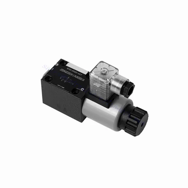
M-SED Series Directional Poppet Hydraulic Valve With Solenoid Actuation
M-SED Series Directional Poppet Hydraulic Valve With Solenoid Actuation
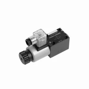
The M-SED series directional poppet hydraulic valve with solenoid actuation is a cutting-edge solution that provides precise control and optimal efficiency in hydraulic systems. With its innovative design, reliable performance, and advanced solenoid actuation, this valve offers enhanced fluid flow control, flexibility, and compatibility with various industrial applications.
The M-SED series directional poppet hydraulic valve with solenoid actuation is a reliable and efficient solution for hydraulic systems. With its directional poppet design, advanced solenoid actuation, versatility, and high flow capacity, this valve offers precise control, enhanced efficiency, and compatibility with various applications. The M-SED series valve delivers optimal performance and reliability by following the recommended usage methods and adhering to regular maintenance practices. Upgrade your hydraulic system with the M-SED series directional poppet hydraulic valve and experience enhanced control, efficiency, and productivity.
M-SED Series Directional Poppet Hydraulic Valve With Solenoid Actuation Key Characteristics:
- Directional Poppet Design:
- The M-SED series valve features a directional poppet design, ensuring reliable and efficient fluid flow control.
- It allows for quick response times and precise regulation of fluid direction, enhancing overall system performance.
- Solenoïde-actuatie:
- This hydraulic valve is equipped with advanced solenoid actuation and provides remote and automated control capabilities.
- The solenoid allows quick and accurate switching between different flow paths, improving operational efficiency.
- Versatility and Compatibility:
- The M-SED series valve is highly versatile and compatible with various hydraulic systems and applications.
- It can be seamlessly integrated into industrial machinery, mobile equipment, and automation systems, enhancing performance.
- Hoge stroomcapaciteit:
- With its robust design and optimized flow paths, the M-SED series valve offers high flow capacity.
- It ensures efficient fluid transfer, reducing pressure drops and maximizing system throughput.
M-SED Series Directional Poppet Hydraulic Valve With Solenoid Actuation Parameter:
| Specificaties | NG6 | NG10 | ||
| Installatiepositie | Optioneel | |||
| Environment temperature | ℃ | -30 tot +50 (NBR-afdichtingen) | ||
| -20 tot +50 (FKM-afdichtingen) | ||||
| Gewicht | Two three-way solenoidic directional valve | kg | 1.5 | 2.6 |
| Two four-way solenoidic directional valve | kg | 2.3 | 3.9 | |
| Maximale werkdruk | bar | 350 | 350 | |
| Max. debiet | L/min | 25 | 40 | |
| Vloeistof | Minerale olie geschikt voor NBR- en FKM-afdichting | |||
| Fosfaatester voor FKM-afdichting | ||||
| Vloeistoftemperatuurbereik | ℃ | -30 tot +80 (NBR-afdichtingen) | ||
| -20 tot +80 (FKM-afdichtingen) | ||||
| Viscositeitsbereik | mm2/S | 2,8 tot 500 | ||
| Mate van verontreiniging | Maximum permissible degree of fluid contamination: Class 9. NAS 1638 | Maximaal toegestane mate van vloeistofverontreiniging: Klasse 9. NAS 1638 of 20/18/15, ISO4406 | ||
M-SED Series Directional Poppet Hydraulic Valve With Solenoid Actuation Advantages:
• Direct solenoid shutoff valve
• Installation face follow DIN 24340 A, ISO 4401 and CETOP-RP 121H
• No leak
• Responsive switching under high pressure
• Het vervangen van de spoel vereist niet het openen van de afgesloten kamer
• Solenoïdespoel kan 90° draaien
• With manual emergency control optional
Usage Method Of M-SED Series Directional Poppet Hydraulic Valve With Solenoid Actuation:
- Systeembeoordeling:
- Conduct a thorough assessment of the hydraulic system to determine the specific requirements and operational parameters.
- Consider factors such as flow rates, pressure ratings, and compatibility with the M-SED Series Valve.
- Klepselectie:
- Select the appropriate M-SED Series Valve variant based on the system requirements and specifications.
- Consider factors such as port size, voltage compatibility, and solenoid actuation parameters.
- Installatie:
- Follow the manufacturer’s instructions for proper installation of the M-SED Series Valve in the hydraulic system.
- Ensure secure mounting, proper alignment, and appropriate sealing to prevent leaks and ensure optimal performance.
- Elektrische aansluitingen:
- Connect the solenoid actuation wires to a suitable power source, following the recommended wiring guidelines.
- Ensure proper polarity and insulation to prevent electrical malfunctions or safety hazards.
How Does A Hydraulic Counterbalance Valve Work?
A hydraulic counterbalance valve is a type of valve used in hydraulic systems to control the motion and stability of loads. It is commonly employed in applications where there is a need to control the descent or lowering of heavy loads, such as in cranes, excavators, and material handling equipment. The primary function of a counterbalance valve is to provide controlled resistance to the downward movement of a load, preventing it from free-falling or dropping uncontrollably.
Here’s how a hydraulic counterbalance valve works:
- Stroomregeling:
- When the load is lifted, hydraulic fluid flows from the pump to the cylinder, raising the load.
- The counterbalance valve is installed in the line between the cylinder and the directional control valve.
- Check Valve Function:
- The counterbalance valve incorporates a built-in check valve that allows the free flow of oil from the pump to the cylinder during the lifting phase.
- The check valve opens, permitting fluid flow in one direction while blocking it in the opposite direction.
- Counterbalance Function:
- When the lifting action is complete and the directional control valve is shifted to the neutral position, the counterbalance valve comes into play.
- As the load starts to descend, the pressure at the cylinder port of the counterbalance valve increases.
- Pilot Pressure:
- The increased pressure at the cylinder port acts on a pilot piston within the counterbalance valve.
- This pilot pressure opposes the spring force in the valve, causing the valve to open gradually.
- Flow Restriction:
- As the counterbalance valve opens, it creates a restricted flow path for the hydraulic fluid returning from the cylinder.
- This restriction slows down the rate of fluid flow, providing controlled resistance against the load’s downward motion.
- Belastingregeling:
- The counterbalance valve modulates the flow restriction based on the load’s weight and the desired speed of descent.
- By adjusting the spring tension or using adjustable counterbalance valves, the valve’s setting can be customized for specific applications.
- Stability and Safety:
- The counterbalance valve ensures stability and safety by preventing the load from dropping too quickly or causing uncontrolled movements.
- It maintains the load in a stable position, even when external forces or variations in the hydraulic system occur.
Vermogen en capaciteit van de fabriek:
(1) Montage
We beschikken over een eersteklas, onafhankelijk R&D-platform voor assemblage. De productiewerkplaats voor hydraulische cilinders beschikt over vier semi-automatische hefcilinderassemblagelijnen en één automatische kantelcilinderassemblagelijn, met een geplande jaarlijkse productiecapaciteit van 1 miljoen stuks. De speciale cilinderwerkplaats is uitgerust met diverse specificaties van een semi-automatisch reinigingsassemblagesysteem met een geplande jaarlijkse productiecapaciteit van 200.000 stuks en is uitgerust met gerenommeerde CNC-bewerkingsapparatuur, een bewerkingscentrum, een zeer nauwkeurige cilinderbewerkingsapparatuur, een robotlasmachine, een automatische reinigingsmachine, een automatische cilinderassemblagemachine en een automatische verfproductielijn. De bestaande kritische apparatuur bestaat uit meer dan 300 sets. De optimale toewijzing en het efficiënte gebruik van apparatuur garanderen de nauwkeurigheidseisen van producten en voldoen aan de hoge kwaliteitseisen.


(2) Bewerking
De bewerkingsruimte is uitgerust met een op maat gemaakt schuin rails draaicentrum, bewerkingscentrum, hogesnelheids hoonmachine, lasrobot en andere bijbehorende apparatuur, die de bewerking van cilinderbuizen met een maximale binnendiameter van 400 mm en een maximale lengte van 6 meter aankan.

(3) Lassen

(4) Schilderen en coaten
Met kleine en middelgrote automatische cilindercoatinglijnen voor watergedragen verf, om automatisch laden en lossen door robots en automatisch spuiten te bereiken, is de ontwerpcapaciteit 4000 stuks per ploegendienst;
Ook beschikken wij over een semi-automatische verfproductielijn voor grote cilinders, aangedreven door een kabelrups, met een ontwerpcapaciteit van 60 dozen per ploeg.


(5) Testen
Wij beschikken over eersteklas inspectiefaciliteiten en testbanken om te garanderen dat de prestaties van de cilinder aan de eisen voldoen.

Wij zijn een van de beste fabrikanten van hydraulische cilinders. We bieden een compleet assortiment hydraulische cilinders. Ook leveren we bijbehorende onderdelen. landbouwversnellingsbakkenWe hebben onze producten wereldwijd geëxporteerd en een goede reputatie opgebouwd dankzij onze superieure productkwaliteit en aftersalesservice. We nodigen klanten in binnen- en buitenland uit om contact met ons op te nemen om zaken te doen, informatie uit te wisselen en werk met ons samen!


