
4WRPEH Series Proportional Directional Hydraulic Valve
4WRPEH Series Proportional Directional Hydraulic Valve
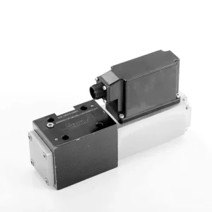
The 4WRPEH series proportional directional hydraulic valve is an advanced hydraulic component designed to deliver exceptional precision and control in hydraulic systems. With its innovative proportional directional control technology, this valve enables accurate flow regulation and smooth directional changes.
The 4WRPEH series proportional directional hydraulic valve empowers hydraulic systems with precise flow control, versatile functionality, and enhanced efficiency. Its proportional directional control technology ensures accurate and responsive flow adjustment, while the high flow capacity guarantees reliable performance even in demanding applications. By following the recommended usage methods and maintenance guidelines, you can maximize the benefits and longevity of the 4WRPEH series valve, elevating your hydraulic system to new levels of precision and control. Upgrade your hydraulic setup today and experience the power of the 4WRPEH series proportional directional hydraulic valve.
4WRPEH Series Proportional Directional Hydraulic Valve Key Characteristics:
- Proportional Directional Control:
- The 4WRPEH series valve utilizes state-of-the-art proportional directional control technology, allowing precise and proportional flow adjustment based on control signals.
- Funkcja ta zapewnia dokładną i responsywną kontrolę, co przekłada się na lepszą wydajność systemu, mniejsze zużycie energii i większą produktywność.
- Wszechstronna funkcjonalność:
- Zawór ten zapewnia wszechstronną kontrolę kierunku przepływu płynu hydraulicznego, dzięki czemu nadaje się do szerokiej gamy zastosowań.
- Umożliwia bezproblemową aktywację i dezaktywację podzespołów hydraulicznych, takich jak cylindry, silniki i siłowniki, w różnych kierunkach, zwiększając elastyczność i zdolność adaptacji systemu.
- Wysoka przepustowość:
- The 4WRPEH series valve is engineered to handle high flow rates, making it ideal for applications that require substantial hydraulic power.
- Solidna konstrukcja gwarantuje niezawodną pracę nawet w trudnych warunkach, gwarantując spójną i wydajną kontrolę przepływu.
- Precise Metering:
- With its proportional control technology, this valve offers precise metering of hydraulic fluid, allowing for accurate control and regulation of flow rates.
- This precision enhances overall system performance and ensures precise movements of hydraulic actuators.
4WRPEH Series Proportional Directional Hydraulic Valve Parameter:
NG6
| Ogólny | |||||||
| Projekt | Spool valve, direct operated, with steel sleeve | ||||||
| Aktywacja | Proportional solenoid with position control, OBE | ||||||
| Typ połączenia | Subplate mounting, porting pattern according to ISO 4401-03-02-0-05 | ||||||
| Pozycja instalacji | Any | ||||||
| Zakres temperatur otoczenia | ℃ | -20…+50 | |||||
| Waga | kg | about 2.75 | |||||
| Maximum vibration resistance (test condition) | Max. 25 g, space vibration test in all directions (24h) | ||||||
| Hydrauliczny (measured at p=100bar, with HLP46 at ϑoil = 40℃ ±5℃) | |||||||
| Płyn ciśnieniowy | Mineral oil (HL, HLP)to DIN 51 524 | ||||||
| Zakres lepkości | zalecony | mm²/s | 20…100 | ||||
| maks. dozwolony | mm²/s | 10…800 | |||||
| Zakres temperatury płynu ciśnieniowego | ℃ | -20 do +70 | |||||
| Maksymalny dopuszczalny stopień zanieczyszczenia płynu ciśnieniowego Klasa czystości wg ISO 4406 (c) | Klasa 18/16/13 | ||||||
| Rated flow (Δp = 35 bar per edge) | l/min | 2 | 4 | 12 | 24 | 40 | |
| Maksymalne ciśnienie robocze | bar | Port A、B、P:315 | |||||
| Max. pressure | bar | Port T: 250 | |||||
| Leakage flow at 100 bar | Linear | cm³/min | <150 | <180 | <300 | <500 | <900; |
| Nonlinear | cm³/min | / | / | / | <300 | <450; | |
| Statyczny/Dynamiczny | |||||||
| Histereza | % | ≤0.2 | |||||
| Actuating time for signal step 0 … 100% | SM | 10 | |||||
| Temperature drift | Zero shift < 1% at ΔT=40℃ | ||||||
| Zero compensation | Ex factory ±1% | ||||||
| Electric, control electronics integrated in the valve | |||||||
| Relative duty cycle | % | 100ED | |||||
| Stopień ochrony | IP65 | ||||||
| Connection | Plug-in connector 6P+PE, DIN 43563 | ||||||
| Supply voltage Terminal A Terminal B |
24VDCnom | ||||||
| min. 21VDC / max. 40VDC | |||||||
| 0V (ripple max. 2) | |||||||
| Fuse protection, external | AF | 2.5 | |||||
| nput, version “A1” Terminal D (UE) Terminal E |
Differential amplifier, Ri = 100 kΩ | ||||||
| 0…±10V | |||||||
| 0V | |||||||
| Input, version “F1” Terminal D (ID-E) Terminal E (ID-E) |
Load, Rsh = 200 Ω | ||||||
| 4…12…20mA | |||||||
| Current loop ID-E return | |||||||
| Test signal, version “A1” Terminal F (UTest) Terminal C |
LVDT | ||||||
| 0…±10V | |||||||
| Reference 0 V | |||||||
| Test signal, version “F1” Terminal F ( I F-C ) Terminal C ( I F-C ) |
LVDT signal 4 … (12) … 20 mA on external load 200 … 500 Ωmaximum | ||||||
| 4 … (12) … 20mA (output) | |||||||
| Current loop IF-C return | |||||||
| Adjustment | Calibrated before delivery, see characteristic curves | ||||||
NG10
| Ogólny | |||||
| Projekt | Spool valve, directly operated, with steel sleeve | ||||
| Aktywacja | Proportional solenoid with position control, OBE | ||||
| Typ połączenia | Plate port, porting pattern (ISO 4401-05-04-0-05) | ||||
| Pozycja instalacji | Any | ||||
| Zakres temperatur okoliczności | ℃ | -20…+50 | |||
| Waga | kg | about 7.1 | |||
| Maximum vibration resistance (test condition) | Max. 25 g, space vibration test in all directions (24h) | ||||
| Hydraulic (measured with HLP 46, ϑoil =40℃ ±5℃) | |||||
| Płyn ciśnieniowy | Hydraulic oil according to DIN 51524…535 | ||||
| Zakres lepkości | zalecony | mm²/s | 20…100 | ||
| Max. permitted | mm²/s | 10…800 | |||
| Zakres temperatury płynu ciśnieniowego | ℃ | -20 do +70 | |||
| Max. admissible degree of contamination of the hydraulic fluid,cleanliness class according to ISO 4406 (c) | Klasa 18/16/13 | ||||
| Rated flow(Δp = 35 bar per edge) | l/min | 50 | 100 | ||
| Maksymalne ciśnienie robocze | bar | Port P A B: 315 | |||
| Max. pressure | bar | Port T: 250 | |||
| Leakage flow at 100 bar | Linear | cm³/min | <1200 | <1500 | |
| Nonlinear | cm³/min | <600 | <600 | ||
| Statyczny/Dynamiczny | |||||
| Histereza | % | ≤0.2 | |||
| Actuating time for signal step 0 … 100% | SM | 25 | |||
| Temperature drift | Zero shift < 1% at ΔT=40℃ | ||||
| Zero compensation | Ex factory ±1% | ||||
| Electric, control electronics integrated in the valve | |||||
| Relative duty cycle | % | 100ED | |||
| Stopień ochrony | IP65(with mating connector mounted and locked ) | ||||
| Connection | Mating connector 6P+PE, DIN 43563 | ||||
| Supply voltage Terminal A Terminal B |
24VDCnom | ||||
| min. 21VDC / max. 40VDC | |||||
| Ripple max. 2 VDC | |||||
| Fuse protection, external | AF | 2.5 | |||
| Input, version “A1” Terminal D (UE) Terminal E |
Differential amplifier, Ri = 100 kΩ | ||||
| 0…±10V | |||||
| 0V | |||||
| Input, version “F1” Terminal D (ID-E) Terminal E (ID-E) |
Load, Rsh = 200 | ||||
| 4…12…20mA | |||||
| Current loop ID-E return | |||||
| Test signal, version “A1” Terminal F (UTest) Terminal C |
LVDT | ||||
| 0…±10V | |||||
| Reference 0 V | |||||
| Test signal, version “F1” Terminal F ( I F-C ) Terminal C ( I F-C ) |
LVDT | ||||
| 4…20 mA output | |||||
| Current loop IF-C feedback | |||||
4WRPEH Series Proportional Directional Hydraulic Valve Advantages:
• Direct-acting servo solenoid valve with control piston and valve sleeve, with servo performance
• Single-side drive, optional with power-off safety function
Control solenoid with built-in feedback and integrated amplifier board (OBE), factory preset
• Electrical connection 6P+PE signal input differential amplifier with interface, input optional A1: ±10V, or interface F1: 4…20mA (Rsh =200Ω)
• Panel mounting, the mounting surface complies with ISO 4401-03-02
Usage Method Of 4WRPEH Series Proportional Directional Hydraulic Valve :
- Ocena systemu:
- Oceń swój układ hydrauliczny i określ szczegółowe wymagania dotyczące przepływu i sterowania kierunkowego.
- Determine if the 4WRPEH series valve is suitable based on its flow capacity, pressure rating, and compatibility with your system.
- Wybór zaworu:
- Select the appropriate variant of the 4WRPEH series valve based on your system parameters, flow requirements, and directional control needs.
- Należy wziąć pod uwagę takie czynniki, jak maksymalna szybkość przepływu, ciśnienie znamionowe, czas reakcji i warunki pracy.
- Instalacja:
- Należy dokładnie przestrzegać instrukcji producenta dotyczących instalacji, aby zapewnić właściwe wyrównanie i bezpieczne zamocowanie zaworu.
- Make leak-free connections and ensure correct flow direction alignment to guarantee optimal performance.
- Podłączenie sygnału sterującego:
- Podłącz przewody sygnału sterującego zaworu do odpowiedniego urządzenia sterującego, na przykład wzmacniacza proporcjonalnego lub elektronicznej jednostki sterującej.
- Należy zadbać o właściwe okablowanie i kompatybilność między zaworem a urządzeniem sterującym, aby zapewnić dokładną i responsywną kontrolę.
How To Hook Two Hydraulic Valves Together?
Hooking two hydraulic valves together requires careful consideration of the valve types, their functions, and the specific hydraulic system requirements. Here are general guidelines on how to hook two hydraulic valves together:
- Identify Valve Types:
- Determine the types of valves you are working with, such as directional control valves, pressure control valves, flow control valves, or any other specific valves required for your system.
- Ensure that both valves are compatible in terms of size, pressure ratings, flow capacity, and function.
- Understand Valve Functions:
- Familiarize yourself with the functions of each valve. For example, directional control valves regulate fluid flow direction, pressure control valves control system pressure, and flow control valves manage flow rates.
- Determine how the combination of these valves will contribute to achieving the desired hydraulic system operation.
- Determine Valve Placement:
- Decide where in the hydraulic system you want to install the two valves. Consider factors such as fluid flow path, pressure requirements, and the desired control sequence.
- Ensure that the valve placement allows for proper fluid flow and accessibility for maintenance and operation.
- Connect Valve Ports:
- Identify the inlet and outlet ports of each valve. These ports may be labeled or indicated in the valve documentation.
- Use appropriate hydraulic fittings, adapters, or connectors to connect the ports of the two valves together.
- Ensure a secure and leak-free connection by using suitable sealing materials, such as O-rings or thread sealants.
- Consider Valve Interactions:
- Evaluate how the interaction between the two valves will affect the hydraulic system’s overall performance.
- Ensure that the combined operation of the valves does not create conflicts or result in unintended consequences, such as pressure spikes, flow restrictions, or unintended movements.
- Control Signal Integration:
- If the valves require control signals, such as electrical or pneumatic signals, determine how these signals will be integrated.
- Connect the control signal lines of both valves to the appropriate control devices, such as hydraulic control modules, electronic control units, or manual control levers.
- Ensure proper wiring, compatibility, and synchronization between the control devices and the valves to achieve the desired control and coordination.
- Test and Adjust:
- After hooking the valves together, thoroughly test the hydraulic system to ensure proper operation.
- Monitor the system for any issues, such as leaks, excessive pressure drops, or unexpected behavior.
- Make necessary adjustments, such as fine-tuning control settings or modifying valve placement if required.
Możliwości i pojemność fabryki:
(1) Montaż
Dysponujemy najwyższej klasy niezależną platformą badawczo-rozwojową. Warsztat produkcji siłowników hydraulicznych posiada cztery półautomatyczne linie montażowe siłowników podnoszących i jedną automatyczną linię montażową siłowników przechyłu, o projektowanej rocznej zdolności produkcyjnej 1 miliona sztuk. Specjalny warsztat cylindrów jest wyposażony w różne specyfikacje półautomatycznego systemu montażu czyszczącego o projektowanej rocznej zdolności produkcyjnej 200 000 i wyposażony w słynny sprzęt do obróbki CNC, centrum obróbcze, specjalny sprzęt do precyzyjnej obróbki cylindrów, robot spawalniczy, automatyczna maszyna czyszcząca, automatyczna maszyna do montażu cylindrów i automatyczna linia produkcyjna do malowania. Istniejący krytyczny sprzęt składa się z ponad 300 zestawów. Optymalna alokacja i efektywne wykorzystanie zasobów sprzętowych zapewniają wymagania dotyczące dokładności produktów i spełniają potrzeby wysokiej jakości produktów.


(2) Obróbka
Warsztat obróbki skrawaniem jest wyposażony w niestandardowe centrum tokarskie z pochyloną szyną, centrum obróbcze, szybkobieżną honownicę, robota spawalniczego i inny powiązany sprzęt, który może obsługiwać przetwarzanie rur cylindrycznych o maksymalnej średnicy wewnętrznej 400 mm i maksymalnej długości 6 metrów.

(3) Spawanie

(4) Malowanie i powlekanie
Z małymi i średnimi automatycznymi liniami do powlekania farbami na bazie wody, w celu osiągnięcia automatycznego załadunku i rozładunku robota oraz automatycznego natryskiwania, wydajność projektowa 4000 sztuk na zmianę;
Posiadamy również półautomatyczną linię do produkcji farb do dużych cylindrów napędzaną łańcuchem napędowym, o wydajności 60 skrzyń na zmianę.


(5) Testowanie
Dysponujemy najwyższej klasy urządzeniami kontrolnymi i stanowiskami testowymi, aby zapewnić, że wydajność cylindra spełnia wymagania.

Jesteśmy jednym z najlepszych producentów cylindrów hydraulicznych. Oferujemy kompleksową ofertę cylindrów hydraulicznych. Dostarczamy również… przekładnie rolnicze. Eksportowaliśmy nasze produkty do klientów na całym świecie i zdobyliśmy dobrą reputację dzięki najwyższej jakości produktów i usług posprzedażnych. Zapraszamy klientów w kraju i za granicą do kontaktu z nami w celu negocjacji biznesowych, wymiany informacji i współpracować z nami!


