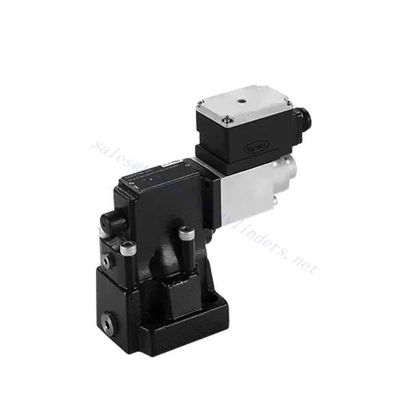
DBE/M(E) Series Proportional Pressure Relief Hydraulic Valve
DBE/M(E) Series Proportional Pressure Relief Hydraulic Valve
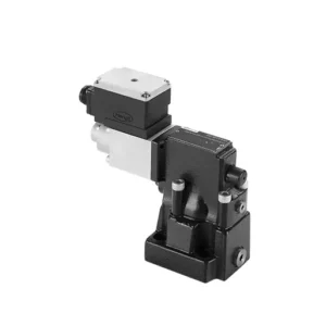
The DBE/M(E) series proportional pressure relief hydraulic valve is a state-of-the-art component designed to deliver precise pressure control in hydraulic systems. With its advanced proportional control technology, this valve ensures optimal performance, efficiency, and safety.
The DBE/M(E) series proportional pressure relief hydraulic valve empowers hydraulic systems with precise pressure control, enhanced efficiency, and equipment protection. With its advanced proportional control technology, this valve ensures optimal performance across various applications. By following the recommended usage methods and maintenance guidelines, you can maximize the benefits and reliability of the DBE/M(E) series valve, elevating the pressure control and overall performance of your hydraulic system. Upgrade your hydraulic setup today and experience superior pressure regulation with the DBE/M(E) series proportional pressure relief hydraulic valve.
DBE6X(E) Series Proportional Pressure Relief Hydraulic Valve Key Characteristics:
- Proportional Pressure Relief:
- The DBE/M(E) series valve offers precise and proportional pressure relief, allowing for dynamic control of hydraulic pressure.
- It ensures accurate pressure regulation in response to varying load conditions, preventing system overload and safeguarding hydraulic components.
- Zwiększona wydajność systemu:
- This valve enables precise hydraulic pressure control, resulting in enhanced system efficiency and reduced energy consumption.
- By maintaining the desired pressure levels, it minimizes pressure fluctuations, optimizes system performance, and reduces operational costs.
- Safety and Equipment Protection:
- The DBE/M(E) series valve acts as a protective mechanism by limiting the pressure within the hydraulic system, safeguarding equipment and operators.
- It prevents excessive pressure build-up, reducing the risk of component damage, system failures, and potential accidents.
- Proportional Control Functionality:
- With its proportional control technology, the DBE/M(E) series valve offers smooth and precise pressure adjustment.
- It allows for real-time pressure control, enabling seamless integration into various hydraulic systems and applications.
DBE/M(E) Series Proportional Pressure Relief Hydraulic Valve Parameter:
| Ogólny | ||||
| Płyn | Olej mineralny odpowiedni do uszczelnień NBR i FKM | |||
| Ester fosforanowy do uszczelnień FKM | ||||
| Zakres temperatur cieczy | ℃ | -30 do +80 (uszczelki NBR) | ||
| -20 do +80 (uszczelki FKM) | ||||
| Zakres lepkości | mm2/S | 2,8 do 380 | ||
| Stopień skażenia | Maksymalny dopuszczalny stopień zanieczyszczenia płynem: Klasa 9. NAS 1638 lub 20/18/15, ISO4406 | |||
| Maksymalne ciśnienie robocze | 315 bar | |||
| Porty A, B, X | bar | 50; 100; 200; 315 | ||
| Maksymalne ciśnienie ustawienia | bar | W odniesieniu do przepływu (Q) patrz krzywe charakterystyczne | ||
| Min. ustawialne ciśnienie | =Minimalne ciśnienie do ustawienia | |||
| Min. ustawialne ciśnienie przy wartości polecenia 0 | Oddzielne i bezciśnieniowe do zbiorników | |||
| Port powrotu ciśnienia oleju Y | bar | Ustawienie ciśnienia | Zakres ciśnienia poniżej maksymalnego ciśnienia bezpieczeństwa | |
| Maksymalne ciśnienie bezpieczeństwa (regulowane bezstopniowo) | 50 bar | 10-60+20 bar | ||
| 100 bar | 10-120+20 bar | |||
| 200 bar | 10-220+20 bar | |||
| 315 bar | 10-340+20 bar | |||
| Maksymalny stan bezpieczeństwa ustawienia ciśnienia | When rated pressure is 50 bar, between 60 bar and 80 bar | |||
| When rated pressure is 100 bar, between120 bar and 140 bar | ||||
| When rated pressure is 200 bar, between 220 bar and 240 bar | ||||
| When rated pressure is 315 bar, between 340 bar and 360 bar | ||||
| Rozmiar | 10 | 25 | 32 | |
| Maksymalny przepływ | 200 | 400 | 600 | |
| Olej pilotowy (do zaworu pilotowego) | l/min | 0,7 do 2 | ||
| Liniowość | l/min | ±3,5% | ||
| Powtarzalność | <±2% | |||
| Histereza | z shimmy | bez shimmy | ||
| ±1,5% P max (200Hz, amplituda 200mAsss) | ±4,5% P max | |||
| Czas przełączania | 30~150ms(independent with the system) | |||
| Dane elektryczne | ||||
| Moc | DC | |||
| Min. prąd elektromagnesu | mama | 100 | ||
| Maksymalny prąd elektromagnesu | mama | 800 | ||
| Rezystancja cewki | 19.5Ω at 20℃, Max. warm value: 28.8Ω | |||
| Status pracy | Ciągły | |||
| Maksymalny zakres temperatur otoczenia | +50℃ | |||
| Połączenie elektryczne | Złącze wtykowe wg DIN 43 650/2 +SL/PG11 | |||
| Izolacja zgodna z DIN 40 050 | IP 65 | |||
| Amplifier | VT2000 | |||
DBE/M(E) Series Proportional Pressure Relief Hydraulic Valve Advantages:
• Stosowany do montażu na dolnej płycie pomocniczej
• Montaż powierzchni czołowej odbywa się zgodnie z normami DIN24340 E i ISO 6264
• Stosowany w montażu bloków kanałów olejowych
• Cztery zakresy ciśnienia
• Konstrukcja zabezpieczająca przed najwyższym ciśnieniem (opcjonalnie)
• Pasujący wzmacniacz elektroniczny typu VT-2000 (należy zamówić osobno)
Usage Method Of DBE/M(E) Series Proportional Pressure Relief Hydraulic Valve:
- Ocena systemu:
- Evaluate your hydraulic system and identify the specific pressure control requirements.
- Determine if the DBE/M(E) series valve is compatible with your system based on its pressure range, flow capacity, and other specifications.
- Wybór zaworu:
- Choose the appropriate DBE/M(E) series valve variant based on your system parameters, pressure range, and flow requirements.
- Należy wziąć pod uwagę maksymalne ciśnienie znamionowe, czas reakcji i warunki operacyjne.
- Instalacja:
- Dokładnie postępuj zgodnie z instrukcjami producenta dotyczącymi instalacji, aby zapewnić właściwe wyrównanie i bezpieczne mocowanie zaworu.
- Podłącz zawór do układu hydraulicznego, upewniając się, że połączenia są szczelne i kierunek przepływu jest prawidłowy.
- Regulacja ciśnienia:
- Utilize the proportional control signal or adjustment mechanism provided with the DBE/M(E) series valve to set the desired pressure relief level.
- Reguluj zawór stopniowo, monitorując wskazania manometru i reakcję układu, aby uzyskać precyzyjną kontrolę ciśnienia.
How To Adjust Hydraulic Pressure Relief Valve?
Adjusting a hydraulic pressure relief valve allows you to regulate the maximum pressure within a hydraulic system. This is important for maintaining system integrity and preventing damage to components. Here’s a step-by-step guide on how to adjust a hydraulic pressure relief valve:
- Identify the Pressure Relief Valve:
- Locate the hydraulic pressure relief valve in your system. It is typically positioned in the hydraulic line or integrated into a manifold block.
- Understand the Valve Design:
- Familiarize yourself with the specific design of the pressure relief valve you are working with. Different valves may have varying adjustment mechanisms, such as a knob, screw, or locknut.
- Determine the Desired Pressure Setting:
- Assess the requirements of your hydraulic system and determine the desired maximum pressure. Consider the system’s specifications, load conditions, and safety limits.
- Przygotuj system:
- Before making any adjustments, shut off the hydraulic system and relieve the pressure by moving the control levers back and forth or following the manufacturer’s recommended procedure.
- Locate the Adjustment Mechanism:
- Identify the adjustment mechanism on the pressure relief valve. It could be a knob, screw, or locknut positioned on the valve body or adjacent to it.
- Adjust the Valve:
- If the valve has a knob or handle, turn it clockwise to increase the pressure relief setting or counterclockwise to decrease it. If the valve has a screw, turn it clockwise to increase the ground or counterclockwise to drop it.
- Wprowadź stopniowe zmiany:
- When adjusting the pressure relief valve, make small, incremental changes to avoid sudden or drastic variations in pressure. This allows you to fine-tune the system and prevent potential damage.
- Observe the System:
- With each adjustment, observe the hydraulic system’s pressure gauge or indicator to see the effect of the changes. Ensure that the pressure stays within the desired range.
- Testuj i weryfikuj:
- Gradually increase the system’s pressure and monitor the pressure relief valve’s response. Ensure it relieves stress when the maximum set pressure is reached and maintains the desired maximum pressure.
- Zablokuj regulację:
- Once you have achieved the desired pressure setting, secure the adjustment mechanism to prevent unintended changes. Some valves may have a locking nut or set screw that can be tightened to hold the adjustment in place.
- Document the Adjustment:
- Keep a record of the adjusted pressure relief setting for future reference and maintenance purposes. This documentation will help maintain consistency and aid troubleshooting efforts.
Możliwości i pojemność fabryki:
(1) Montaż
Dysponujemy najwyższej klasy niezależną platformą badawczo-rozwojową. Warsztat produkcji siłowników hydraulicznych posiada cztery półautomatyczne linie montażowe siłowników podnoszących i jedną automatyczną linię montażową siłowników przechyłu, o projektowanej rocznej zdolności produkcyjnej 1 miliona sztuk. Specjalny warsztat cylindrów jest wyposażony w różne specyfikacje półautomatycznego systemu montażu czyszczącego o projektowanej rocznej zdolności produkcyjnej 200 000 i wyposażony w słynny sprzęt do obróbki CNC, centrum obróbcze, specjalny sprzęt do precyzyjnej obróbki cylindrów, robot spawalniczy, automatyczna maszyna czyszcząca, automatyczna maszyna do montażu cylindrów i automatyczna linia produkcyjna do malowania. Istniejący krytyczny sprzęt składa się z ponad 300 zestawów. Optymalna alokacja i efektywne wykorzystanie zasobów sprzętowych zapewniają wymagania dotyczące dokładności produktów i spełniają potrzeby wysokiej jakości produktów.


(2) Obróbka
Warsztat obróbki skrawaniem jest wyposażony w niestandardowe centrum tokarskie z pochyloną szyną, centrum obróbcze, szybkobieżną honownicę, robota spawalniczego i inny powiązany sprzęt, który może obsługiwać przetwarzanie rur cylindrycznych o maksymalnej średnicy wewnętrznej 400 mm i maksymalnej długości 6 metrów.

(3) Spawanie

(4) Malowanie i powlekanie
Z małymi i średnimi automatycznymi liniami do powlekania farbami na bazie wody, w celu osiągnięcia automatycznego załadunku i rozładunku robota oraz automatycznego natryskiwania, wydajność projektowa 4000 sztuk na zmianę;
Posiadamy również półautomatyczną linię do produkcji farb do dużych cylindrów napędzaną łańcuchem napędowym, o wydajności 60 skrzyń na zmianę.


(5) Testowanie
Dysponujemy najwyższej klasy urządzeniami kontrolnymi i stanowiskami testowymi, aby zapewnić, że wydajność cylindra spełnia wymagania.

Jesteśmy jednym z najlepszych producentów cylindrów hydraulicznych. Oferujemy kompleksową ofertę cylindrów hydraulicznych. Dostarczamy również… przekładnie rolnicze. Eksportowaliśmy nasze produkty do klientów na całym świecie i zdobyliśmy dobrą reputację dzięki najwyższej jakości produktów i usług posprzedażnych. Zapraszamy klientów w kraju i za granicą do kontaktu z nami w celu negocjacji biznesowych, wymiany informacji i współpracować z nami!


