

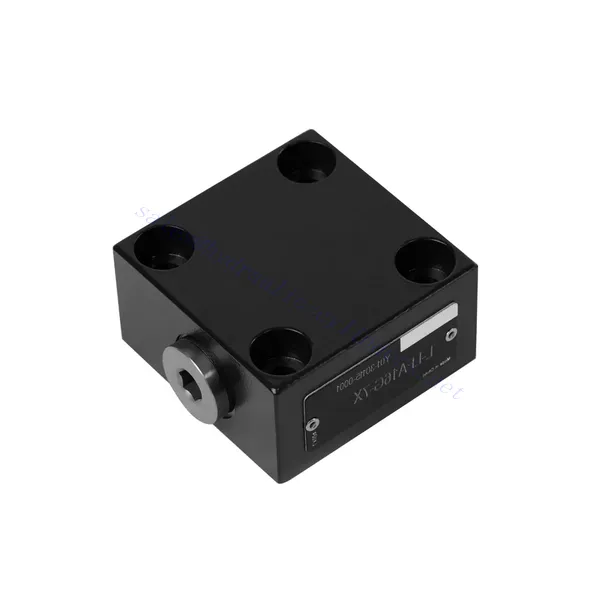
Válvula hidráulica de controle direcional da série L-LFA
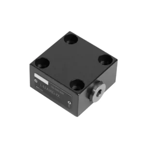

A válvula hidráulica de controle direcional da série L-LFA é um componente de ponta projetado para oferecer controle preciso e desempenho ideal em sistemas hidráulicos. Com seus recursos avançados e construção robusta, esta válvula proporciona controle direcional confiável e eficiente para diversas aplicações.
A válvula hidráulica de controle direcional da série L-LFA é um divisor de águas para sistemas hidráulicos, oferecendo controle direcional preciso, versatilidade e durabilidade. Seguindo os métodos de uso e as diretrizes de manutenção recomendadas, você poderá aproveitar todo o potencial da válvula da série L-LFA e experimentar maior controle, eficiência e produtividade em suas aplicações hidráulicas. Atualize seu sistema hidráulico hoje mesmo e desbloqueie as vantagens da precisão e da eficiência com a válvula hidráulica de controle direcional da série L-LFA.
Principais características da válvula hidráulica de controle direcional da série L-LFA:
- Controle direcional preciso:
- A válvula da série L-LFA oferece um controle direcional excepcional, permitindo o gerenciamento preciso e eficiente do fluxo de fluidos em sistemas hidráulicos.
- Essa característica permite que os operadores direcionem o fluido hidráulico para atuadores ou componentes hidráulicos específicos, facilitando um movimento suave e controlado.
- Opções de configuração versáteis:
- Esta válvula está disponível em várias configurações, incluindo opções de 2, 3 e 4 vias, garantindo compatibilidade com os diversos requisitos de sistemas hidráulicos.
- A configuração de 2 vias facilita o controle simples de ligar/desligar, enquanto as configurações de 3 e 4 vias permitem funções mais complexas, como extensão e retração do cilindro, além de controle bidirecional.
- Construção de Alto Desempenho:
- A válvula da série L-LFA é projetada com materiais de alta qualidade e técnicas de fabricação de precisão para garantir durabilidade e longa vida útil.
- Sua construção robusta permite que ele suporte altas pressões, variações de temperatura e condições operacionais severas, garantindo um desempenho confiável mesmo em ambientes exigentes.
- Tempo de resposta rápido:
- Esta válvula possui um tempo de resposta impressionante, permitindo um controle rápido e eficiente do fluxo de fluido dentro do sistema hidráulico.
- O tempo de resposta rápido facilita ajustes precisos e imediatos, resultando em melhor desempenho do sistema e menor consumo de energia.
Parâmetros da válvula hidráulica de controle direcional da série L-LFA:
| Pressão máxima de trabalho | Sem válvula direcional | bar | 420 | |||||
| – Posto de petróleo A, B, X, Z1, Z2 | bar | 315; 350; 420 (Depende da válvula direcional montada na parte superior) | ||||||
| – Porto petrolífero Y | bar | Equivalente à pressão de retorno de uma válvula direcional montada na parte superior. | ||||||
| Fluido | Óleo mineral adequado para vedação NBR e FKM | |||||||
| Éster de fosfato para selo FKM | ||||||||
| Faixa de temperatura do fluido | °C | -30 a +80 (vedação NBR) | ||||||
| -20 a +80 (selo FKM) | ||||||||
| Faixa de viscosidade | milímetros2/s | 2,8 a 380 | ||||||
| Grau de contaminação | Grau máximo permitido de contaminação do fluido: Classe 9. NAS 1638 ou 20/18/15, ISO 4406 | |||||||
Vantagens da válvula hidráulica de controle direcional da série L-LFA:
• Tipo básico D com controle remoto
• Com limitador de curso H
• Válvula de transferência integrada G
• Válvula direcional de sede integrada R, RF
• Pode ser equipado com válvula direcional WE
Método de utilização da válvula hidráulica de controle direcional da série L-LFA:
- Avaliação do Sistema:
- Avalie seu sistema hidráulico e identifique os requisitos específicos de controle direcional.
- Determine se a válvula da série L-LFA é adequada para o seu sistema com base nas taxas de fluxo, classificações de pressão e compatibilidade com a sua aplicação.
- Seleção de válvulas:
- Selecione a variante apropriada da válvula da série L-LFA com base nos parâmetros do seu sistema e nas suas necessidades de controle direcional.
- Considere fatores como o tipo de válvula (2 vias, 3 vias ou 4 vias), a capacidade de vazão, a pressão nominal e a compatibilidade com sua aplicação específica.
- Instalação:
- Siga atentamente as instruções de instalação do fabricante para garantir o alinhamento correto e a montagem segura da válvula.
- Utilize conexões hidráulicas, adaptadores e vedações compatíveis para garantir conexões sem vazamentos. Aperte as conexões adequadamente, evitando o aperto excessivo que possa danificar a válvula ou as conexões.
- Integração de sistemas:
- Conecte as linhas hidráulicas às portas apropriadas da válvula da série L-LFA, garantindo a direção correta do fluxo.
- Verifique se a válvula está instalada na orientação correta, conforme indicado pelas setas direcionais no corpo da válvula.
- Operação e Controle:
- Familiarize-se com os mecanismos de controle da válvula da série L-LFA, como alavancas, botões ou solenoides.
- Certifique-se de que a válvula esteja acionada corretamente e que o fluxo hidráulico desejado seja alcançado com base nos requisitos do sistema.
Como instalar uma válvula de alívio de pressão hidráulica?
A instalação de uma válvula de alívio de pressão hidráulica é uma etapa crucial para garantir a segurança e o funcionamento adequado de um sistema hidráulico. Aqui está um guia passo a passo sobre como instalar uma válvula de alívio de pressão hidráulica:
- Identifique a válvula: Determine o tipo e modelo específicos da válvula de alívio de pressão hidráulica que você utiliza. Certifique-se de que ela seja adequada para sua aplicação e compatível com os requisitos do seu sistema hidráulico.
- Reúna as ferramentas e materiais necessários: Reúna as ferramentas e os materiais necessários, incluindo conexões hidráulicas apropriadas, adaptadores, chaves, fita de Teflon (selante de rosca) e um manômetro, se necessário. Consulte as instruções do fabricante para obter informações sobre as ferramentas ou componentes específicos necessários.
- Prepare o sistema hidráulico: Desligue o sistema hidráulico e alivie a pressão acionando a válvula de alívio ou retraindo os cilindros hidráulicos. Esta etapa é crucial para a segurança e evita movimentos acidentais ou vazamento de fluido hidráulico.
- Identifique o ponto de alívio de pressão: Determine a localização ideal para instalar a válvula de alívio de pressão hidráulica em seu sistema hidráulico. Ela deve ser posicionada a jusante da bomba, antes de quaisquer componentes sensíveis, para protegê-los da pressão excessiva. Consulte o esquema do sistema hidráulico ou procure aconselhamento profissional, se necessário.
- Monte a válvula: Monte a válvula de alívio de pressão hidráulica com segurança no local escolhido, utilizando suportes ou braçadeiras apropriadas. Certifique-se de que a válvula esteja posicionada corretamente, alinhando as portas de entrada e saída com a direção do fluxo. Siga as instruções do fabricante para os requisitos específicos de montagem.
- Conecte as portas de entrada e saída: Conecte mangueiras ou tubos hidráulicos às portas de entrada e saída da válvula de alívio. Utilize conexões e adaptadores hidráulicos adequados para garantir uma conexão sem vazamentos. Aplique fita de Teflon ou selante de rosca nas roscas macho das conexões para assegurar uma vedação segura. Aperte as conexões com chaves para evitar vazamentos, mas tome cuidado para não apertar demais.
- Ajuste a configuração de alívio de pressão: A maioria das válvulas de alívio de pressão hidráulica possui um ajuste de pressão. Ajuste a válvula de alívio para o ponto de pressão desejado, seguindo as instruções do fabricante. Algumas válvulas podem exigir um manômetro para ajustar a pressão de alívio com precisão. Se necessário, instale o manômetro temporariamente e ajuste a válvula de alívio até atingir a pressão desejada.
- Teste o sistema: Após a instalação da válvula de alívio de pressão hidráulica, restabeleça lentamente a pressão do sistema hidráulico. Monitore o manômetro ou observe o comportamento do sistema para garantir que a válvula de alívio esteja funcionando corretamente. A válvula de alívio deve abrir e desviar o excesso de pressão quando atingir o ponto de ajuste, evitando danos ao sistema.
- Monitorar e manter: Inspecione regularmente a válvula de alívio de pressão hidráulica para verificar se há sinais de vazamento, danos ou desempenho reduzido. Limpe a válvula e a área ao redor para remover sujeira e detritos que possam afetar seu funcionamento. Siga o cronograma e as diretrizes de manutenção recomendadas pelo fabricante para garantir o desempenho ideal e a longevidade do equipamento.
Aptidão e capacidade da fábrica:
(1) Montagem
Temos uma plataforma de montagem de pesquisa e desenvolvimento independente de primeira classe. A oficina de produção de cilindros hidráulicos tem quatro linhas de montagem semiautomáticas de cilindros de elevação e uma linha de montagem automática de cilindros de inclinação, com uma capacidade de produção anual projetada de 1 milhão de peças. A oficina de cilindros especiais é equipada com várias especificações de um sistema de montagem de limpeza semiautomática com uma capacidade de produção anual projetada de 200.000 peças e equipada com famosos equipamentos de usinagem CNC, um centro de usinagem, um equipamento especial de processamento de cilindros de alta precisão, uma máquina de solda robotizada, uma máquina de limpeza automática, uma máquina de montagem automática de cilindros e uma linha de produção de pintura automática. O equipamento crítico existente é de mais de 300 conjuntos (conjuntos). A alocação ideal e o uso eficiente dos recursos do equipamento garantem os requisitos de precisão dos produtos e atendem às necessidades de alta qualidade dos produtos.


(2) Usinagem
A oficina de usinagem é equipada com um centro de torneamento de trilho inclinado personalizado, um centro de usinagem, uma máquina de brunimento de alta velocidade, um robô de soldagem e outros equipamentos relacionados, que podem lidar com o processamento de tubos de cilindros com diâmetro interno máximo de 400 mm e comprimento máximo de 6 metros.


(3) Soldagem


(4) Pintura e revestimento
Com linhas de revestimento de tinta à base de água automáticas de cilindros de pequeno e médio porte, para obter carregamento e descarregamento automáticos de robôs e pulverização automática, a capacidade projetada é de 4.000 peças por turno;
Também temos uma linha de produção de tinta semiautomática para cilindros grandes, acionada por uma corrente elétrica, com capacidade de projeto de 60 caixas por turno.


(5) Testes
Temos instalações de inspeção e bancos de teste de primeira classe para garantir que o desempenho do cilindro atenda aos requisitos.


Somos um dos melhores fabricantes de cilindros hidráulicos. Oferecemos cilindros hidráulicos completos. Também fornecemos os correspondentes caixas de câmbio agrícolas. Exportamos nossos produtos para clientes em todo o mundo e conquistamos uma boa reputação devido à qualidade superior de nossos produtos e ao serviço pós-venda. Convidamos clientes nacionais e estrangeiros a entrar em contato conosco para negociar negócios, trocar informações e cooperar conosco!