Válvula hidráulica direcional da série WMM com acionamento mecânico e manual.
Válvula hidráulica direcional da série WMM com acionamento mecânico e manual.
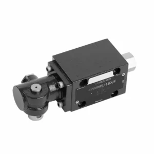
The WMM series directional hydraulic valve with mechanical, manual operation is a versatile and reliable solution designed to control hydraulic systems precisely. This hydraulic valve offers enhanced efficiency and flexibility with its advanced features and robust construction.
The WMM series directional hydraulic valve with mechanical, manual operation is a reliable and versatile solution for hydraulic systems. Its automatic manual operation and precise directional control offer enhanced flexibility and control for various applications. Following the recommended usage methods and adhering to regular maintenance practices, the WMM series hydraulic valve will continue providing efficient and reliable operation. Upgrade your hydraulic system with the WMM series directional valve and experience the benefits of enhanced control and versatility.
WMM Series Directional Hydraulic Valve With Mechanical, Manual Operation Key Characteristics:
- Operação mecânica e manual:
- The WMM series hydraulic valve features a mechanical, manual operation, allowing operators to control the valve position manually.
- Isso proporciona flexibilidade e controle em aplicações onde a operação manual é desejada ou necessária.
- Controle direcional:
- Esta válvula hidráulica permite o controle preciso do fluxo de fluido direcional dentro do sistema hidráulico.
- Ele permite que os operadores selecionem o caminho de fluxo desejado, garantindo uma operação eficiente e confiável.
- Construção durável:
- The WMM series hydraulic valve is constructed with high-quality materials, ensuring durability and longevity.
- Seu design robusto pode suportar condições operacionais exigentes, proporcionando desempenho confiável.
- Compact Size:
- The valve’s compact size allows easy integration into hydraulic systems with limited space.
- It is ideal for applications where space is a constraint without compromising performance.
WMM Series Directional Hydraulic Valve With Mechanical, Manual Operation Parameter:
NG6
| Faixa de temperatura do fluido | °C | -30 a +80 (vedações NBR) | |
| -20 a +80 (vedações FKM) | |||
| Pressão máxima de operação da porta | Porto ABP | bar | 315 |
| Porto T | bar | 160 | |
| Taxa de fluxo máxima | L/min | 60 | |
| Flowarea (troca de posição neutra) | Tipo Q | milímetros2 | Para o símbolo Q, 6% da seção transversal nominal |
| Tipo W | milímetros2 | Para o símbolo W, 3% da seção transversal nominal | |
| Fluido | Óleo mineral; Éster de fosfato | ||
| Faixa de viscosidade | milímetros2/s | 2,8 a 500 | |
| Grau de contaminação | Grau máximo permitido de contaminação do fluido: Classe 9. NAS 1638 ou 20/18/15, ISO4406 | ||
| Peso | kg | 1.6 | |
NG10
| Faixa de temperatura do fluido | °C | -30 a +80 (vedações NBR) | |
| -20 a +80 (vedações FKM) | |||
| Pressão máxima de operação da porta | Porto ABP | bar | 315 |
| Porto T | bar | 160 | |
| Taxa de fluxo máxima | L/min | 120 | |
| Seção transversal do fluxo (posição neutra de comutação) | Tipo V | milímetros2 | 11(A/B → T);10.3(P → A/B) |
| Tipo W | milímetros2 | 2,5(A/B → T) | |
| Tipo Q | milímetros2 | 5,5(A/B → T) | |
| Fluido | Óleo mineral; Éster de fosfato | ||
| Faixa de viscosidade | milímetros2/s | 2,8 a 500 | |
| Grau de contaminação | Grau máximo permitido de contaminação do fluido: Classe 9. NAS 1638 ou 20/18/15, ISO4406 | ||
| Peso | kg | 4.4 | |
NG16-32
| NS | 16 | 25 | 32 |
| Peso | about 8 | about 12.2 | about 49 |
| Actuation force with detent N | about 75 | about 105 | about 170 |
| with spring return N | |||
| Actuation angle about the neutral position | 2*26° | 2*32° | 2*30° |
| Max. operating pressure Port A,B,P bar | 315 | ||
| Port T bar | 250 | ||
| Fluido | Óleo mineral adequado para vedação NBR e FKM | ||
| Phosphate ester – for FKM seal | |||
| Faixa de temperatura do fluido | -30 to +80(NBR seal) | ||
| -20 a +80 (selo FKM) | |||
| Viscosity range mm2/s | 2.8 to 380 | ||
| Grau de contaminação | Grau máximo permitido de contaminação do fluido: Classe 9. NAS 1638 ou 20/18/15, ISO4406 | ||
WMM Series Directional Hydraulic Valve With Mechanical, Manual Operation Advantages:
• Válvula de deslizamento direcional de ação direta Válvula de deslizamento direcional de ação direta
• Sub-plate mounting
• Handle control
• Installation face follow DIN 24340 A, ISO 4401
Usage Method Of WMM Series Directional Hydraulic Valve With Mechanical, Manual Operation:
- Integração de sistemas:
- Identify the appropriate location for the WMM series hydraulic valve within the hydraulic system, considering the desired flow direction and control requirements.
- Garanta a compatibilidade com as especificações de pressão e fluxo do sistema.
- Monte a válvula com segurança usando suportes ou acessórios de montagem apropriados.
- Conexões de fluidos:
- Selecione conexões hidráulicas e mangueiras compatíveis para conexões seguras e sem vazamentos.
- Siga as instruções do fabricante para obter valores de torque adequados durante o processo de instalação.
- Use selantes de rosca ou fita apropriados para garantir uma vedação confiável.
- Operação manual:
- Familiarize yourself with the manual operation mechanism of the valve, including the lever or knob used to control the hydraulic valve position.
- Certifique-se de que o operador entenda o procedimento correto para ajustar manualmente a posição da válvula.
- Calibração do sistema:
- Calibrate the hydraulic valve position and movement according to the desired flow direction and control requirements.
- Ajuste a válvula manualmente para atingir o caminho de fluxo desejado e garantir a funcionalidade adequada.
How To Adjust Valves On A Hydraulic Roller Cam?
Adjusting valves on a hydraulic roller cam requires careful attention to detail and following the proper procedure. Here’s a step-by-step guide to help you adjust the valves correctly:
- Prepare o motor:
- Ensure the engine is turned off and cool to the touch before starting the adjustment process.
- Locate the valve covers and remove them to access the valve train components.
- Identifique a sequência correta de ajuste da válvula:
- Consulte as especificações do fabricante do motor ou o manual de serviço para determinar a sequência correta de ajuste de válvulas para seu motor específico.
- Localize a posição do ponto morto superior (TDC):
- Rotate the engine’s crankshaft in the normal direction of rotation until the number one piston reaches the top dead center position on its compression stroke.
- Use a timing mark on the harmonic balancer or flywheel and a timing pointer to identify the TDC position accurately.
- Adjusting Valve Lash:
- Begin with the first cylinder in the valve adjustment sequence.
- Loosen the lock nut on the rocker arm stud using an appropriate wrench or socket.
- Use a feeler gauge of the recommended thickness specified by the engine manufacturer to check the valve lash (clearance) between the rocker arm and the valve stem.
- Slide the feeler gauge between the rocker arm and the valve stem. You should feel slight resistance but still be able to move the gauge back and forth.
- Adjust the valve lash by either tightening or loosening the rocker arm stud until the proper clearance is achieved. Turning the stud clockwise decreases the clearance, while counterclockwise increases it.
- Once you’ve set the correct valve lash, hold the rocker arm stud in place and tighten the lock nut securely.
- Repita o processo:
- Move to the next cylinder in the valve adjustment sequence and repeat steps 4 and 5 until all the valves have been adjusted.
- Reinstale as tampas das válvulas:
- Depois de concluir o ajuste das válvulas em todos os cilindros, reinstale as tampas das válvulas e certifique-se de que estejam devidamente vedadas para evitar vazamentos de óleo.
- Verifique novamente:
- After adjusting the valves, it’s a good practice to go through the entire valve adjustment sequence once more to confirm that all clearances are within the specified range.
Aptidão e capacidade da fábrica:
(1) Montagem
Temos uma plataforma de montagem de pesquisa e desenvolvimento independente de primeira classe. A oficina de produção de cilindros hidráulicos tem quatro linhas de montagem semiautomáticas de cilindros de elevação e uma linha de montagem automática de cilindros de inclinação, com uma capacidade de produção anual projetada de 1 milhão de peças. A oficina de cilindros especiais é equipada com várias especificações de um sistema de montagem de limpeza semiautomática com uma capacidade de produção anual projetada de 200.000 peças e equipada com famosos equipamentos de usinagem CNC, um centro de usinagem, um equipamento especial de processamento de cilindros de alta precisão, uma máquina de solda robotizada, uma máquina de limpeza automática, uma máquina de montagem automática de cilindros e uma linha de produção de pintura automática. O equipamento crítico existente é de mais de 300 conjuntos (conjuntos). A alocação ideal e o uso eficiente dos recursos do equipamento garantem os requisitos de precisão dos produtos e atendem às necessidades de alta qualidade dos produtos.


(2) Usinagem
A oficina de usinagem é equipada com um centro de torneamento de trilho inclinado personalizado, um centro de usinagem, uma máquina de brunimento de alta velocidade, um robô de soldagem e outros equipamentos relacionados, que podem lidar com o processamento de tubos de cilindros com diâmetro interno máximo de 400 mm e comprimento máximo de 6 metros.

(3) Soldagem

(4) Pintura e revestimento
Com linhas de revestimento de tinta à base de água automáticas de cilindros de pequeno e médio porte, para obter carregamento e descarregamento automáticos de robôs e pulverização automática, a capacidade projetada é de 4.000 peças por turno;
Também temos uma linha de produção de tinta semiautomática para cilindros grandes, acionada por uma corrente elétrica, com capacidade de projeto de 60 caixas por turno.


(5) Testes
Temos instalações de inspeção e bancos de teste de primeira classe para garantir que o desempenho do cilindro atenda aos requisitos.

Somos um dos melhores fabricantes de cilindros hidráulicos. Oferecemos cilindros hidráulicos completos. Também fornecemos os correspondentes caixas de câmbio agrícolas. Exportamos nossos produtos para clientes em todo o mundo e conquistamos uma boa reputação devido à qualidade superior de nossos produtos e ao serviço pós-venda. Convidamos clientes nacionais e estrangeiros a entrar em contato conosco para negociar negócios, trocar informações e cooperar conosco!