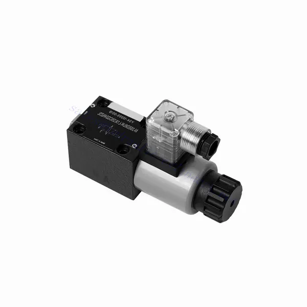
Válvula hidráulica direcional tipo poppet da série M-SED com acionamento por solenóide
Válvula hidráulica direcional tipo poppet da série M-SED com acionamento por solenóide
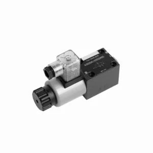
The M-SED series directional poppet hydraulic valve with solenoid actuation is a cutting-edge solution that provides precise control and optimal efficiency in hydraulic systems. With its innovative design, reliable performance, and advanced solenoid actuation, this valve offers enhanced fluid flow control, flexibility, and compatibility with various industrial applications.
The M-SED series directional poppet hydraulic valve with solenoid actuation is a reliable and efficient solution for hydraulic systems. With its directional poppet design, advanced solenoid actuation, versatility, and high flow capacity, this valve offers precise control, enhanced efficiency, and compatibility with various applications. The M-SED series valve delivers optimal performance and reliability by following the recommended usage methods and adhering to regular maintenance practices. Upgrade your hydraulic system with the M-SED series directional poppet hydraulic valve and experience enhanced control, efficiency, and productivity.
M-SED Series Directional Poppet Hydraulic Valve With Solenoid Actuation Key Characteristics:
- Directional Poppet Design:
- The M-SED series valve features a directional poppet design, ensuring reliable and efficient fluid flow control.
- It allows for quick response times and precise regulation of fluid direction, enhancing overall system performance.
- Atuação do Solenóide:
- This hydraulic valve is equipped with advanced solenoid actuation and provides remote and automated control capabilities.
- The solenoid allows quick and accurate switching between different flow paths, improving operational efficiency.
- Versatilidade e compatibilidade:
- The M-SED series valve is highly versatile and compatible with various hydraulic systems and applications.
- It can be seamlessly integrated into industrial machinery, mobile equipment, and automation systems, enhancing performance.
- Alta capacidade de fluxo:
- With its robust design and optimized flow paths, the M-SED series valve offers high flow capacity.
- It ensures efficient fluid transfer, reducing pressure drops and maximizing system throughput.
M-SED Series Directional Poppet Hydraulic Valve With Solenoid Actuation Parameter:
| Especificações | NG6 | NG10 | ||
| Posição de instalação | Opcional | |||
| Temperatura ambiente | °C | -30 a +50 (vedações NBR) | ||
| -20 a +50 (vedações FKM) | ||||
| Peso | Two three-way solenoidic directional valve | Kg | 1.5 | 2.6 |
| Two four-way solenoidic directional valve | Kg | 2.3 | 3.9 | |
| Pressão máxima de operação | bar | 350 | 350 | |
| Taxa de fluxo máxima | L/min | 25 | 40 | |
| Fluido | Óleo mineral adequado para vedação NBR e FKM | |||
| Éster de fosfato para selo FKM | ||||
| Faixa de temperatura do fluido | °C | -30 a +80 (vedações NBR) | ||
| -20 a +80 (vedações FKM) | ||||
| Faixa de viscosidade | milímetros2/s | 2,8 a 500 | ||
| Grau de contaminação | Maximum permissible degree of fluid contamination: Class 9. NAS 1638 | Grau máximo permitido de contaminação do fluido: Classe 9. NAS 1638 ou 20/18/15, ISO4406 | ||
M-SED Series Directional Poppet Hydraulic Valve With Solenoid Actuation Advantages:
• Direct solenoid shutoff valve
• A face de instalação segue as normas DIN 24340 A, ISO 4401 e CETOP-RP 121H.
• No leak
• Responsive switching under high pressure
• A substituição da bobina não requer a abertura da câmara selada
• A bobina solenóide pode girar 90°
• With manual emergency control optional
Usage Method Of M-SED Series Directional Poppet Hydraulic Valve With Solenoid Actuation:
- Avaliação do Sistema:
- Conduct a thorough assessment of the hydraulic system to determine the specific requirements and operational parameters.
- Consider factors such as flow rates, pressure ratings, and compatibility with the M-SED Series Valve.
- Seleção de válvulas:
- Select the appropriate M-SED Series Valve variant based on the system requirements and specifications.
- Consider factors such as port size, voltage compatibility, and solenoid actuation parameters.
- Instalação:
- Follow the manufacturer’s instructions for proper installation of the M-SED Series Valve in the hydraulic system.
- Ensure secure mounting, proper alignment, and appropriate sealing to prevent leaks and ensure optimal performance.
- Conexões elétricas:
- Connect the solenoid actuation wires to a suitable power source, following the recommended wiring guidelines.
- Ensure proper polarity and insulation to prevent electrical malfunctions or safety hazards.
How Does A Hydraulic Counterbalance Valve Work?
A hydraulic counterbalance valve is a type of valve used in hydraulic systems to control the motion and stability of loads. It is commonly employed in applications where there is a need to control the descent or lowering of heavy loads, such as in cranes, excavators, and material handling equipment. The primary function of a counterbalance valve is to provide controlled resistance to the downward movement of a load, preventing it from free-falling or dropping uncontrollably.
Here’s how a hydraulic counterbalance valve works:
- Controle de fluxo:
- When the load is lifted, hydraulic fluid flows from the pump to the cylinder, raising the load.
- The counterbalance valve is installed in the line between the cylinder and the directional control valve.
- Check Valve Function:
- The counterbalance valve incorporates a built-in check valve that allows the free flow of oil from the pump to the cylinder during the lifting phase.
- The check valve opens, permitting fluid flow in one direction while blocking it in the opposite direction.
- Counterbalance Function:
- When the lifting action is complete and the directional control valve is shifted to the neutral position, the counterbalance valve comes into play.
- As the load starts to descend, the pressure at the cylinder port of the counterbalance valve increases.
- Pilot Pressure:
- The increased pressure at the cylinder port acts on a pilot piston within the counterbalance valve.
- This pilot pressure opposes the spring force in the valve, causing the valve to open gradually.
- Flow Restriction:
- As the counterbalance valve opens, it creates a restricted flow path for the hydraulic fluid returning from the cylinder.
- This restriction slows down the rate of fluid flow, providing controlled resistance against the load’s downward motion.
- Load Control:
- The counterbalance valve modulates the flow restriction based on the load’s weight and the desired speed of descent.
- By adjusting the spring tension or using adjustable counterbalance valves, the valve’s setting can be customized for specific applications.
- Stability and Safety:
- The counterbalance valve ensures stability and safety by preventing the load from dropping too quickly or causing uncontrolled movements.
- It maintains the load in a stable position, even when external forces or variations in the hydraulic system occur.
Aptidão e capacidade da fábrica:
(1) Montagem
Temos uma plataforma de montagem de pesquisa e desenvolvimento independente de primeira classe. A oficina de produção de cilindros hidráulicos tem quatro linhas de montagem semiautomáticas de cilindros de elevação e uma linha de montagem automática de cilindros de inclinação, com uma capacidade de produção anual projetada de 1 milhão de peças. A oficina de cilindros especiais é equipada com várias especificações de um sistema de montagem de limpeza semiautomática com uma capacidade de produção anual projetada de 200.000 peças e equipada com famosos equipamentos de usinagem CNC, um centro de usinagem, um equipamento especial de processamento de cilindros de alta precisão, uma máquina de solda robotizada, uma máquina de limpeza automática, uma máquina de montagem automática de cilindros e uma linha de produção de pintura automática. O equipamento crítico existente é de mais de 300 conjuntos (conjuntos). A alocação ideal e o uso eficiente dos recursos do equipamento garantem os requisitos de precisão dos produtos e atendem às necessidades de alta qualidade dos produtos.


(2) Usinagem
A oficina de usinagem é equipada com um centro de torneamento de trilho inclinado personalizado, um centro de usinagem, uma máquina de brunimento de alta velocidade, um robô de soldagem e outros equipamentos relacionados, que podem lidar com o processamento de tubos de cilindros com diâmetro interno máximo de 400 mm e comprimento máximo de 6 metros.

(3) Soldagem

(4) Pintura e revestimento
Com linhas de revestimento de tinta à base de água automáticas de cilindros de pequeno e médio porte, para obter carregamento e descarregamento automáticos de robôs e pulverização automática, a capacidade projetada é de 4.000 peças por turno;
Também temos uma linha de produção de tinta semiautomática para cilindros grandes, acionada por uma corrente elétrica, com capacidade de projeto de 60 caixas por turno.


(5) Testes
Temos instalações de inspeção e bancos de teste de primeira classe para garantir que o desempenho do cilindro atenda aos requisitos.

Somos um dos melhores fabricantes de cilindros hidráulicos. Oferecemos cilindros hidráulicos completos. Também fornecemos os correspondentes caixas de câmbio agrícolas. Exportamos nossos produtos para clientes em todo o mundo e conquistamos uma boa reputação devido à qualidade superior de nossos produtos e ao serviço pós-venda. Convidamos clientes nacionais e estrangeiros a entrar em contato conosco para negociar negócios, trocar informações e cooperar conosco!