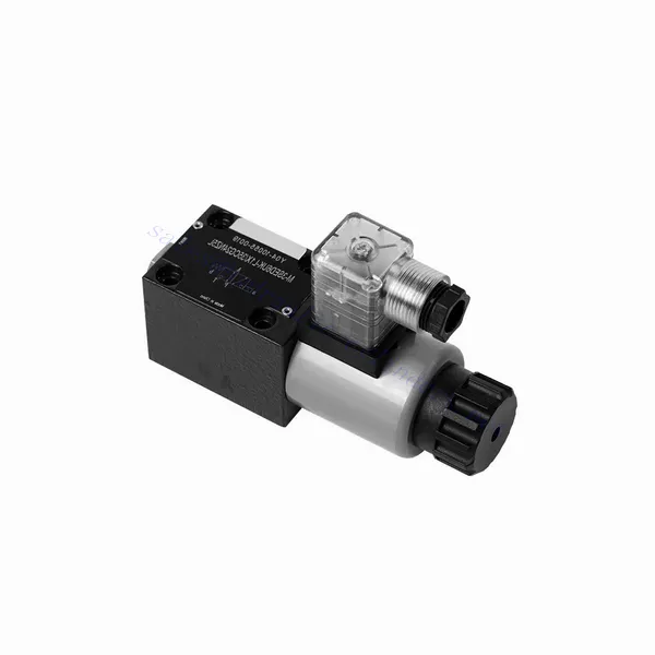
M-SED Series Directional Poppet Hydraulic Valve With Solenoid Actuation
M-SED Series Directional Poppet Hydraulic Valve With Solenoid Actuation
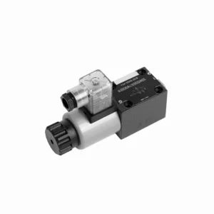
The M-SED series directional poppet hydraulic valve with solenoid actuation is a cutting-edge solution that provides precise control and optimal efficiency in hydraulic systems. With its innovative design, reliable performance, and advanced solenoid actuation, this valve offers enhanced fluid flow control, flexibility, and compatibility with various industrial applications.
The M-SED series directional poppet hydraulic valve with solenoid actuation is a reliable and efficient solution for hydraulic systems. With its directional poppet design, advanced solenoid actuation, versatility, and high flow capacity, this valve offers precise control, enhanced efficiency, and compatibility with various applications. The M-SED series valve delivers optimal performance and reliability by following the recommended usage methods and adhering to regular maintenance practices. Upgrade your hydraulic system with the M-SED series directional poppet hydraulic valve and experience enhanced control, efficiency, and productivity.
M-SED Series Directional Poppet Hydraulic Valve With Solenoid Actuation Key Characteristics:
- Directional Poppet Design:
- The M-SED series valve features a directional poppet design, ensuring reliable and efficient fluid flow control.
- It allows for quick response times and precise regulation of fluid direction, enhancing overall system performance.
- Ovládanie solenoidom:
- This hydraulic valve is equipped with advanced solenoid actuation and provides remote and automated control capabilities.
- The solenoid allows quick and accurate switching between different flow paths, improving operational efficiency.
- Versatility and Compatibility:
- The M-SED series valve is highly versatile and compatible with various hydraulic systems and applications.
- It can be seamlessly integrated into industrial machinery, mobile equipment, and automation systems, enhancing performance.
- Vysoká prietoková kapacita:
- With its robust design and optimized flow paths, the M-SED series valve offers high flow capacity.
- It ensures efficient fluid transfer, reducing pressure drops and maximizing system throughput.
M-SED Series Directional Poppet Hydraulic Valve With Solenoid Actuation Parameter:
| Špecifikácie | NG6 | NG10 | ||
| Montážna poloha | Voliteľné | |||
| Teplota prostredia | ℃ | -30 až +50 (tesnenia NBR) | ||
| -20 až +50 (tesnenia FKM) | ||||
| Hmotnosť | Two three-way solenoidic directional valve | kg | 1.5 | 2.6 |
| Two four-way solenoidic directional valve | kg | 2.3 | 3.9 | |
| Maximálny prevádzkový tlak | bar | 350 | 350 | |
| Max. prietok | l/min | 25 | 40 | |
| Tekutina | Minerálny olej vhodný pre tesnenia NBR a FKM | |||
| Fosfátový ester pre tesnenie FKM | ||||
| Rozsah teploty kvapaliny | ℃ | -30 až +80 (tesnenia NBR) | ||
| -20 až +80 (tesnenia FKM) | ||||
| Rozsah viskozity | mm2/s | 2,8 až 500 | ||
| Stupeň kontaminácie | Maximum permissible degree of fluid contamination: Class 9. NAS 1638 | Maximálny povolený stupeň kontaminácie kvapaliny: Trieda 9. NAS 1638 alebo 20/18/15, ISO4406 | ||
M-SED Series Directional Poppet Hydraulic Valve With Solenoid Actuation Advantages:
• Direct solenoid shutoff valve
• Montážna plocha zodpovedá normám DIN 24340 A, ISO 4401 a CETOP-RP 121H
• No leak
• Responsive switching under high pressure
• Výmena cievky nevyžaduje otvorenie utesnenej komory
• Cievka solenoidu sa môže otáčať o 90°
• With manual emergency control optional
Usage Method Of M-SED Series Directional Poppet Hydraulic Valve With Solenoid Actuation:
- Posúdenie systému:
- Conduct a thorough assessment of the hydraulic system to determine the specific requirements and operational parameters.
- Consider factors such as flow rates, pressure ratings, and compatibility with the M-SED Series Valve.
- Výber ventilu:
- Select the appropriate M-SED Series Valve variant based on the system requirements and specifications.
- Consider factors such as port size, voltage compatibility, and solenoid actuation parameters.
- Inštalácia:
- Follow the manufacturer’s instructions for proper installation of the M-SED Series Valve in the hydraulic system.
- Ensure secure mounting, proper alignment, and appropriate sealing to prevent leaks and ensure optimal performance.
- Elektrické pripojenia:
- Connect the solenoid actuation wires to a suitable power source, following the recommended wiring guidelines.
- Ensure proper polarity and insulation to prevent electrical malfunctions or safety hazards.
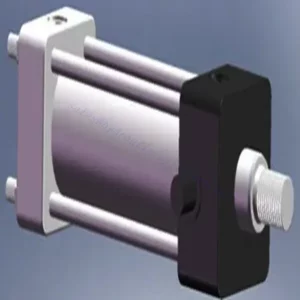
How Does A Hydraulic Counterbalance Valve Work?
A hydraulic counterbalance valve is a type of valve used in hydraulic systems to control the motion and stability of loads. It is commonly employed in applications where there is a need to control the descent or lowering of heavy loads, such as in cranes, excavators, and material handling equipment. The primary function of a counterbalance valve is to provide controlled resistance to the downward movement of a load, preventing it from free-falling or dropping uncontrollably.
Here’s how a hydraulic counterbalance valve works:
- Riadenie prietoku:
- When the load is lifted, hydraulic fluid flows from the pump to the cylinder, raising the load.
- The counterbalance valve is installed in the line between the cylinder and the directional control valve.
- Check Valve Function:
- The counterbalance valve incorporates a built-in check valve that allows the free flow of oil from the pump to the cylinder during the lifting phase.
- The check valve opens, permitting fluid flow in one direction while blocking it in the opposite direction.
- Counterbalance Function:
- When the lifting action is complete and the directional control valve is shifted to the neutral position, the counterbalance valve comes into play.
- As the load starts to descend, the pressure at the cylinder port of the counterbalance valve increases.
- Pilot Pressure:
- The increased pressure at the cylinder port acts on a pilot piston within the counterbalance valve.
- This pilot pressure opposes the spring force in the valve, causing the valve to open gradually.
- Flow Restriction:
- As the counterbalance valve opens, it creates a restricted flow path for the hydraulic fluid returning from the cylinder.
- This restriction slows down the rate of fluid flow, providing controlled resistance against the load’s downward motion.
- Ovládanie záťaže:
- The counterbalance valve modulates the flow restriction based on the load’s weight and the desired speed of descent.
- By adjusting the spring tension or using adjustable counterbalance valves, the valve’s setting can be customized for specific applications.
- Stability and Safety:
- The counterbalance valve ensures stability and safety by preventing the load from dropping too quickly or causing uncontrolled movements.
- It maintains the load in a stable position, even when external forces or variations in the hydraulic system occur.
Schopnosť a kapacita továrne:
(1) Montáž
Disponujeme prvotriednou nezávislou výskumnou a vývojovou montážnou platformou. Dielňa na výrobu hydraulických valcov má štyri poloautomatické montážne linky zdvíhacích valcov a jednu automatickú montážnu linku naklápacích valcov s projektovanou ročnou výrobnou kapacitou 1 milión kusov. Dielňa na výrobu špeciálnych valcov je vybavená rôznymi špecifikáciami poloautomatického systému čistenia a montáže s projektovanou ročnou výrobnou kapacitou 200 000 kusov a je vybavená známym CNC obrábacím zariadením, obrábacím centrom, špeciálnym zariadením na vysoko presné spracovanie valcov, robotickým zváracím strojom, automatickým čistiacim strojom, automatickým montážnym strojom valcov a automatickou lakovacou výrobnou linkou. Existujúce kritické zariadenia majú viac ako 300 súprav (sád). Optimálne alokovanie a efektívne využívanie zdrojov zariadení zabezpečuje požiadavky na presnosť výrobkov a spĺňa požiadavky na vysokú kvalitu výrobkov.


(2) Obrábanie
Obrábacia dielňa je vybavená prispôsobeným sústružníckym centrom na šikmé koľajnice, obrábacím centrom, vysokorýchlostným honovacím strojom, zváracím robotom a ďalším súvisiacim zariadením, ktoré dokáže spracovať valcové rúry s maximálnym vnútorným priemerom 400 mm a maximálnou dĺžkou 6 metrov.

(3) Zváranie

(4) Maľovanie a natieranie
S malými a stredne veľkými valcovými automatickými linkami na nanášanie farieb na vodnej báze, na dosiahnutie automatického nakladania a vykladania robotmi a automatického striekania, je projektovaná kapacita 4000 kusov za smenu;
Máme tiež poloautomatickú linku na výrobu farieb pre veľké valce poháňané reťazou s projektovanou kapacitou 60 kusov za smenu.


(5) Testovanie
Disponujeme prvotriednymi kontrolnými zariadeniami a skúšobnými zariadeniami, ktoré zabezpečujú, že výkonnosť valca spĺňa požiadavky.

Sme jedným z najlepších výrobcov hydraulických valcov. Ponúkame komplexné hydraulické valce. Poskytujeme aj zodpovedajúce poľnohospodárske prevodovkyNaše produkty sme vyvážali klientom po celom svete a vďaka vynikajúcej kvalite produktov a popredajnému servisu sme si získali dobrú reputáciu. Vítame zákazníkov doma aj v zahraničí, ktorí nás kontaktujú za účelom rokovania o obchodných záležitostiach, výmeny informácií a spolupracovať s nami!