
Valvă hidraulică direcțională seria WMR cu acționare mecanică, manuală
Valvă hidraulică direcțională seria WMR cu acționare mecanică, manuală
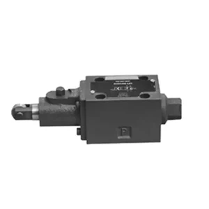
The WMR series directional hydraulic valve with mechanical, manual operation is a cutting-edge solution designed to deliver precise control in hydraulic systems. This valve offers enhanced efficiency and flexibility with its advanced features and robust construction.
The WMR series directional hydraulic valve with mechanical, manual operation is a reliable and versatile solution for hydraulic systems. Its automatic and manual operation and precise directional control offer enhanced flexibility and control for various applications. Following the recommended usage methods and adhering to regular maintenance practices, the WMR series valve will continue providing efficient and reliable operation. Upgrade your hydraulic system with the WMR series directional hydraulic valve and experience the benefits of enhanced control and versatility.
WMR Series Directional Hydraulic Valve With Mechanical, Manual Operation Key Characteristics:
- Mechanical, Manual Operation:
- The WMR series valve features a mechanical, manual operation, allowing operators to control the valve position manually.
- This provides flexibility and control in applications where manual operation is desired or required.
- Control direcțional:
- This hydraulic valve enables precise directional fluid flow control within the hydraulic system.
- It allows operators to select the desired flow path, ensuring efficient and reliable operation.
- Construcție durabilă:
- The WMR series valve is constructed with high-quality materials, ensuring durability and longevity.
- Its robust design can withstand demanding operating conditions, providing reliable performance.
- Wide Range of Applications:
- The WMR series valve suits various industries and applications, including manufacturing, construction, agriculture, etc.
- It can be utilized in hydraulic systems that require accurate and efficient fluid control.
WMR Series Directional Hydraulic Valve With Mechanical, Manual Operation Parameter:
NG6
| Poziția de instalare | Opțional | ||
| Interval de temperatură al fluidului | ℃ | -30 până la +80 (etanșări NBR) | |
| -20 până la +80 (etanșări FKM) | |||
| Presiune maximă de funcționare a orificiului | Portul ABP | bar | 315 |
| Portul T | bar | 60 | |
| Debit maxim | L/min | 60 | |
| Secțiune transversală a curgerii (poziție neutră de comutare) | Tipul Q | mm2 | Pentru simbolul Q, 6% al secțiunii transversale nominale |
| Tip W | mm2 | Pentru simbolul W, 3% al secțiunii transversale nominale | |
| Fluid | Ulei mineral; Ester fosfat | ||
| Interval de vâscozitate | mm2/s | 2,8 până la 500 | |
| Gradul de contaminare | Grad maxim admis de contaminare a fluidului: Clasa 9. NAS 1638 sau 20/18/15, ISO4406 | ||
| Greutate | kg | 1.4 | |
NG10
| Poziția de instalare | Opțional | ||
| Interval de temperatură al fluidului | ℃ | -30 până la +80 (etanșări NBR) | |
| -20 până la +80 (etanșări FKM) | |||
| Presiune maximă de funcționare a orificiului | Portul ABP | bar | 315 |
| Portul T | bar | 60 | |
| Debit maxim | L/min | 120 | |
| Secțiune transversală a curgerii (poziție neutră de comutare) | Tip V | mm2 | 11(A/B → T); 10.3(P → A/B) |
| Tip W | mm2 | 2.5(A/B → T) | |
| Tipul Q | mm2 | 5.5 (A/B → T) | |
| Fluid | Ulei mineral; Ester fosfat | ||
| Interval de vâscozitate | mm2/s | 2,8 până la 500 | |
| Gradul de contaminare | Grad maxim admis de contaminare a fluidului: Clasa 9. NAS 1638 sau 20/18/15, ISO4406 | ||
| Greutate | kg | 4 | |
WMR Series Directional Hydraulic Valve With Mechanical, Manual Operation Advantages:
• Supapă glisantă direcțională cu acțiune directă supapă glisantă direcțională cu acțiune directă
• Rotița de derulare se poate roti la 90°
• Nouăsprezece funcții standard ale valvei glisante
Usage Method Of WMR Series Directional Hydraulic Valve With Mechanical, Manual Operation:
- Integrare de sistem:
- Identify the appropriate location for the WMR series valve within the hydraulic system, considering the desired flow direction and control requirements.
- Asigurați compatibilitatea cu specificațiile de presiune și debit ale sistemului.
- Montați supapa în siguranță folosind console sau accesorii de montare adecvate.
- Conexiuni fluide:
- Selectați fitinguri și furtunuri hidraulice compatibile pentru conexiuni sigure și fără scurgeri.
- Urmați instrucțiunile producătorului pentru valorile corecte ale cuplului în timpul procesului de instalare.
- Use appropriate thread sealants or tape to ensure a reliable seal.
- Manual Operation:
- Familiarize yourself with the manual operation mechanism of the valve, including the lever or knob used to control the valve position.
- Ensure the operator understands the correct procedure for manually adjusting the valve position.
- Calibrarea sistemului:
- Calibrate the valve position and movement according to the desired flow direction and control requirements.
- Adjust the valve manually to achieve the desired flow path and ensure proper functionality.
How To Adjust Hydraulic Valve Lifters?
Adjusting hydraulic valve lifters is a crucial maintenance task to ensure proper engine performance and prevent issues like valve train noise and reduced power. Here’s a step-by-step guide on how to adjust hydraulic valve lifters:
- Prepare the Engine:
- Before starting the adjustment process, make sure the engine is turned off and cool to the touch.
- Remove any components necessary to access the valve covers, such as the air cleaner assembly or spark plug wires.
- Identify the Correct Valve Adjustment Sequence:
- Consult the engine manufacturer’s specifications or service manual to determine the correct valve adjustment sequence for your specific engine.
- Some engines have a firing order that dictates the sequence, while others have specific instructions based on cylinder numbering.
- Locate the Top Dead Center (TDC) Position:
- Rotate the engine’s crankshaft in the normal direction of rotation until the number one piston reaches the top dead center (TDC) position on its compression stroke.
- Use a timing mark on the harmonic balancer or flywheel and a timing pointer to determine the TDC position accurately.
- Adjusting Valve Lifters:
- Start with the first cylinder in the valve adjustment sequence.
- Remove the valve cover to access the rocker arms and valve lifters.
- Loosen the lock nut on the rocker’s arm using an appropriate wrench or socket.
- Turn the adjusting screw or stud on the rocker’s arm clockwise to decrease the valve clearance or counterclockwise to increase it.
- Check the engine manufacturer’s specifications for the recommended valve clearance. Use a feeler gauge to measure the clearance between the rocker arm and the valve stem.
- Adjust the valve lifter until the proper clearance is achieved. You should feel slight resistance but still be able to move the feeler gauge back and forth.
- Hold the adjusting screw or stud in place and tighten the lock nut securely.
- Repetați procesul:
- Move to the next cylinder in the valve adjustment sequence and repeat steps 4 and 5 until all the valve lifters have been adjusted.
- Reinstall Valve Covers:
- Once you’ve completed the valve adjustment on all cylinders, reinstall the valve covers and ensure they are properly sealed to prevent oil leaks.
- Double-Check:
- After adjusting the valve lifters, it’s advisable to go through the entire valve adjustment sequence once more to confirm that all clearances are within the specified range.
Capabilitatea și capacitatea fabricii:
(1) Montaj
Avem o platformă de asamblare independentă de cercetare și dezvoltare de primă clasă. Atelierul de producție a cilindrilor hidraulici are patru linii de asamblare semiautomate pentru cilindri de ridicare și o linie de asamblare automată a cilindrilor de înclinare, cu o capacitate de producție anuală proiectată de 1 milion de bucăți. Atelierul de cilindri speciali este echipat cu diverse specificații ale unui sistem de asamblare semi-automat de curățare, cu o capacitate de producție anuală proiectată de 200.000 și dotat cu echipamente celebre de prelucrare CNC, un centru de prelucrare, un echipament special de prelucrare a cilindrilor de înaltă precizie, o mașină de sudură robotizată, o mașină de curățare automată, o mașină de asamblare automată a cilindrilor și o linie de producție automată de vopsire. Echipamente critice existente de peste 300 de seturi (seturi). Alocarea optimă și utilizarea eficientă a resurselor de echipamente asigură cerințele de precizie ale produselor și satisface nevoile de înaltă calitate ale produselor.


(2) Prelucrare
Atelierul de prelucrare este echipat cu un centru de strunjire cu șină înclinată personalizat, un centru de prelucrare, o mașină de honuire de mare viteză, un robot de sudură și alte echipamente conexe, care pot gestiona prelucrarea tuburilor cilindrice cu un diametru interior maxim de 400 mm și o lungime maximă de 6 metri.

(3) Sudură

(4) Vopsire și acoperire
Cu linii automate de acoperire cu vopsea pe bază de apă cu cilindru de dimensiuni mici și medii, pentru a realiza încărcarea și descărcarea automată a robotului și pulverizarea automată, capacitatea de proiectare de 4000 de bucăți pe schimb;
Avem, de asemenea, o linie de producție semi-automată de vopsire pentru cilindri mari, acționată de un lanț de putere, cu o capacitate de proiectare de 60 de cutii pe schimb.


(5) Testarea
Dispunem de instalații de inspecție și bancuri de testare de primă clasă pentru a ne asigura că performanța cilindrului îndeplinește cerințele.

Suntem unul dintre cei mai buni producători de cilindri hidraulici. Putem oferi o gamă completă de cilindri hidraulici. De asemenea, oferim... cutii de viteze agricoleNe-am exportat produsele către clienți din întreaga lume și ne-am câștigat o bună reputație datorită calității superioare a produselor noastre și a serviciilor post-vânzare. Îi invităm pe clienții din țară și din străinătate să ne contacteze pentru a negocia afaceri, a face schimb de informații și... să coopereze cu noi!


