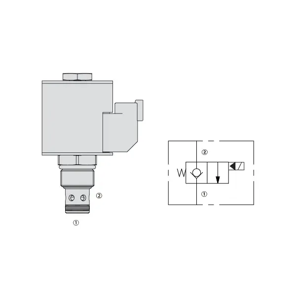
35SD10-20 Solenoid Directional Valve
Являясь одним из производителей, поставщиков и экспортеров механической продукции, мы предлагаем гидравлические цилиндры и многие другие изделия.
Пожалуйста, свяжитесь с нами для получения подробной информации.
Почта:sales@hydraulic-cylinders.net
Производитель поставщик экспортер гидроцилиндров.
35SD10-20 Solenoid Directional Valve
The 35SD10-20 Solenoid Directional Valve is a powerful and versatile component designed to optimize fluid control in a wide range of industrial applications. With its advanced features, precise operation, and reliable performance, this solenoid valve is a valuable tool for enhancing fluid control efficiency and productivity. Whether in manufacturing, automation, or process control, the 35SD10-20 Solenoid Directional Valve delivers exceptional functionality and versatility, making it an essential component for modern industries.
The 30SD08-47D Solenoid Directional Valve is a reliable and versatile component that optimizes fluid control in various industrial applications. With its robust construction, precise fluid control, versatility, and space-efficient design, this solenoid valve offers exceptional performance, ensuring efficient and reliable operations. By incorporating the 30SD08-47D Solenoid Directional Valve into fluid control systems, industries can achieve enhanced productivity, accuracy, and system performance. Invest in this advanced solenoid valve to optimize your industrial processes, streamline operations, and achieve success in your industry.
35SD10-20 Solenoid Directional Valve Characteristics:
- Robust Construction: The 35SD10-20 Solenoid Directional Valve is built with a robust and durable design, ensuring long-lasting performance even in demanding environments. Its sturdy construction allows it to withstand high pressures, temperature fluctuations, and harsh conditions, providing consistent and reliable operation.
- Precise Fluid Control: This solenoid valve offers precise control over fluid flow, enabling accurate and efficient regulation of liquids or gases. With its responsive solenoid mechanism, the valve allows for fast and reliable switching between different flow paths, ensuring precise control and minimizing flow disruptions.
- Versatile Functionality: The 35SD10-20 Solenoid Directional Valve is designed to accommodate various applications in different industries. It can be used for direction control, on/off switching, and pressure regulation, providing flexibility and adaptability in fluid control systems.
- Efficient Energy Consumption: This solenoid valve is designed with energy efficiency in mind. It minimizes power consumption during operation, resulting in cost savings and environmental benefits. The valve’s efficient energy usage makes it a sustainable choice for businesses looking to optimize their resource utilization.
35SD10-20 Solenoid Directional Valve Parameter:
| Номинальное давление | 241 bar (3500 psi) | |
| Пиковый поток | 56.8 L/min (15 gpm) ; See performance chart | |
| Жидкость | На минеральной основе или синтетические со смазывающими свойствами | |
| Диапазон температур жидкости ℃ | -54 до 107 ℃ (Полиуретановые уплотнения) | |
| -40 до 100 ℃ (уплотнения Buna N) | ||
| -26 до 204 ℃ (фторуглеродные уплотнения) | ||
| Диапазон вязкости | 7,4–420 мм2/с | |
| Степень загрязнения | Минимальный уровень загрязнения — ISO4406 18/16/13, для продления срока службы рекомендуется уровень 15/13/11. | |
| Внутренняя утечка | ≤ 0.15 mL/min (3 drops /min) @241 bar | |
| Полость | ВК10-2 | |
| Номинальная нагрузка катушки | Непрерывный от 85% до 115% номинального напряжения | |
| Начальный ток катушки при 20℃ | Электронная катушка | 1,7 А при 12 В постоянного тока; 0,85 А при 24 В постоянного тока |
| D-катушка | 1,67 А при 12 В постоянного тока; 0,83 А при 24 В постоянного тока | |
| Минимальное напряжение втягивания | 85% of nominal at 241 bar | |
35SD10-20 Solenoid Directional Valve Advantages:
• Катушка, рассчитанная на непрерывную работу
• Эффективная конструкция с мокрой арматурой
• Картриджи взаимозаменяемы по напряжению
• Дополнительные водонепроницаемые электронные катушки со степенью защиты до IP69K
• Общая полость в промышленности
• Закаленные детали для длительного срока службы и минимальной утечки
Usage Method Of 35SD10-20 Solenoid Directional Valve:
Установка:
- Follow the manufacturer’s instructions for proper installation of the 35SD10-20 Solenoid Directional Valve.
- Ensure correct alignment and connection to the fluid control system, using appropriate fittings and seals for leak-free operation.
Электрические соединения:
- Connect the solenoid valve to the power supply, following the specified voltage and electrical requirements.
- Ensure proper wiring and insulation to ensure safe and reliable electrical operation.
Направление потока жидкости:
- Determine the desired fluid flow direction based on your application requirements.
- The 35SD10-20 Solenoid Directional Valve provides various ports and positions for inlet, outlet, and exhaust. Consult the product documentation for correct port connections.
Control Signal:
- Connect the control signal, whether electrical or pneumatic, to the solenoid valve to activate its switching mechanism.
- Ensure that the control signal is compatible with the valve’s specifications and operating parameters.
How To Hook Up A Hydraulic Flow Control Valve?
To hook up a hydraulic flow control valve, follow these steps:
- Identify Valve Type: Determine the specific type of flow control valve you are working with. Common types include needle valves, adjustable flow control valves, or pressure-compensated flow control valves. Ensure that the valve is suitable for your application and compatible with your hydraulic system.
- Gather Required Tools and Materials: Collect the necessary tools and materials, including appropriate hydraulic fittings, adapters, hoses, and wrenches.
- Подготовьте гидравлическую систему: Shut down the hydraulic system and relieve any pressure in the system by activating the relief valve or retracting any hydraulic cylinders. This step is crucial for safety.
- Identify Flow Direction: Identify the flow direction in your hydraulic system. Typically, the flow direction is indicated by arrows on the hydraulic components. Ensure that you understand the correct flow direction before proceeding.
- Locate Installation Point: Determine the optimal location to install the flow control valve in your hydraulic system. Consider factors such as accessibility, proximity to the actuator or hydraulic component, and ease of adjustment.
- Установите клапан: Securely mount the flow control valve in the chosen location using appropriate brackets or clamps. Ensure the valve is positioned correctly, aligning the inlet and outlet ports with the flow direction.
- Подключите входной и выходной порты: Attach hydraulic hoses or tubing to the inlet and outlet ports of the flow control valve. Use suitable hydraulic fittings and adapters to create a leak-free connection. Tighten the connections using wrenches to ensure a secure fit, but avoid over-tightening.
- Adjust the Flow Control: Depending on the type of flow control valve, it may have adjustable features such as a needle valve or a flow control knob. Adjust the valve according to your desired flow rate or speed. Refer to the manufacturer’s instructions for specific adjustment procedures.
- Протестируйте систему: Once the flow control valve is installed and adjusted, slowly restore hydraulic system pressure. Test the system to ensure that the flow control valve is functioning correctly. Monitor the flow rate or speed of the hydraulic actuator to verify that it is within the desired range.
- Fine-tune and Monitor: Adjust the flow control valve to achieve the desired flow rate or speed. Regularly monitor the hydraulic system for leaks, pressure inconsistencies, or unusual behavior.
Возможности и мощности завода:
(1) Сборка
Мы располагаем первоклассной независимой сборочной платформой для проведения исследований и разработок. Цех по производству гидравлических цилиндров имеет четыре полуавтоматические линии сборки подъемных цилиндров и одну автоматическую линию сборки цилиндров наклона с проектной годовой производственной мощностью 1 млн. штук. Цех по производству специальных цилиндров оснащен полуавтоматической очистной сборочной системой различных спецификаций с проектной годовой производственной мощностью 200 тыс. штук и оснащен известным обрабатывающим оборудованием с ЧПУ, обрабатывающим центром, высокоточным специальным оборудованием для обработки цилиндров, роботом-сварщиком, автоматической очистной машиной, автоматической сборочной машиной цилиндров и автоматической покрасочной производственной линией. Существующее критически важное оборудование насчитывает более 300 комплектов (комплектов). Оптимальное распределение и эффективное использование ресурсов оборудования позволяет обеспечить требования к точности изделий и удовлетворить потребности в высоком качестве продукции.


(2) Механическая обработка
Цех оснащен специализированным токарным центром с наклонной направляющей, обрабатывающим центром, высокоскоростным хонинговальным станком, сварочным роботом и другим сопутствующим оборудованием, которое позволяет обрабатывать цилиндрические трубы с максимальным внутренним диаметром 400 мм и максимальной длиной 6 м.

(3) Сварка

(4) Покраска и покрытие
С помощью небольших и средних цилиндрических автоматических линий нанесения лакокрасочных материалов на водной основе, обеспечивающих автоматическую загрузку и выгрузку роботом и автоматическое распыление, проектная производительность составляет 4000 изделий в смену;
У нас также имеется полуавтоматическая линия по производству краски для больших баллонов, приводимая в действие электроцепью, с проектной мощностью 60 ящиков в смену.


(5) Тестирование
У нас имеются первоклассные инспекционные центры и испытательные стенды, позволяющие гарантировать соответствие эксплуатационных характеристик цилиндра установленным требованиям.

Мы являемся одним из лучших производителей гидроцилиндров. Мы предлагаем широкий ассортимент гидроцилиндров. Мы также предлагаем сопутствующие товары. сельскохозяйственные редукторыМы экспортируем нашу продукцию клиентам по всему миру и заслужили хорошую репутацию благодаря превосходному качеству продукции и послепродажному обслуживанию. Мы приглашаем клиентов из Китая и других стран связаться с нами для деловых переговоров, обмена информацией и сотрудничать с нами!
Применение гидравлического цилиндра:
