

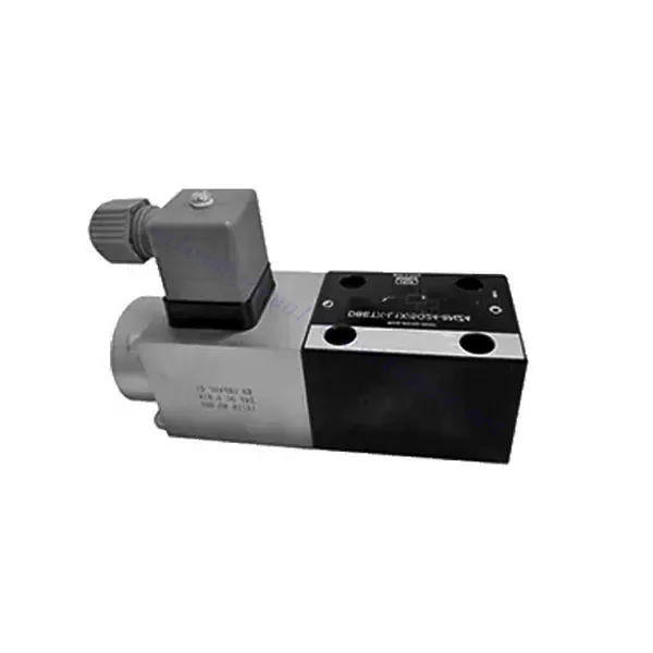
DBETX Series Proportional Pressure Relief Hydraulic Valve
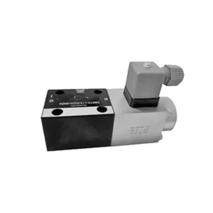

The DBETX series proportional pressure relief hydraulic valve is a versatile and high-performance hydraulic component designed to provide precise pressure relief in hydraulic systems. Engineered with advanced proportional control technology, this valve ensures optimal performance, efficiency, and safety.
The DBETX series proportional pressure relief hydraulic valve empowers hydraulic systems with precise pressure control, enhanced efficiency, and equipment protection. With its proportional pressure relief capabilities, this valve ensures optimal performance across a wide range of applications. By following the recommended usage methods and maintenance guidelines, you can maximize the benefits and reliability of the DBETX series valve, elevating the performance and control of your hydraulic system. Upgrade your hydraulic setup today and experience superior pressure regulation with the DBETX series proportional pressure relief hydraulic valve.
DBETX Series Proportional Pressure Relief Hydraulic Valve Key Characteristics:
- Proportional Pressure Relief:
- The DBETX series valve delivers proportional pressure relief, allowing for accurate and dynamic hydraulic pressure control.
- It ensures precise pressure regulation in response to varying load conditions, preventing damage to hydraulic components and optimizing system performance.
- Повышение эффективности системы:
- This valve enables precise control of hydraulic flow rates, resulting in enhanced system efficiency and reduced energy consumption.
- Maintaining the desired pressure levels minimizes pressure fluctuations, enhances overall productivity, and reduces operational costs.
- Safety and Equipment Protection:
- The DBETX series valve acts as a safeguard by limiting the pressure within the hydraulic system, protecting equipment and operators from potential damage or accidents.
- It prevents overloading and ensures the longevity of hydraulic components, reducing the risk of system failures and downtime.
- Широкий спектр применения:
- With its versatile design and compatibility with various hydraulic systems, the DBETX series valve can be used in a wide range of applications across industries such as manufacturing, construction, agriculture, and more.
- It offers flexibility and adaptability, making it suitable for diverse hydraulic setups and requirements.
DBETX Series Proportional Pressure Relief Hydraulic Valve Parameter:
| General | ||||||
| Строительство | Poppet valve, direct drive | |||||
| Actuation | Proportional solenoid without position control, external amplifier | |||||
| Connection type | Subplate, mounting hole configuration NG6 (ISO 4401-03-02-0-94) | |||||
| Положение установки | Необязательный | |||||
| Диапазон температур при определенных обстоятельствах | ℃ | -20…+50 | ||||
| Масса | Кг | about 2.1 | ||||
| Vibration resistance, test condition | Max. 25 g, shaken in 3 dimensions(24 h) | |||||
| Hydraulic (measured with HLP 46, Voil=40℃±5℃) | ||||||
| Pressure fluid | Hydraulic oil to DIN 51524…535, other fluids after prior consultation | |||||
| Диапазон вязкости | recommended | 20…100 | ||||
| max. permitted | 10…800 | |||||
| Pressure fluid temperature range | ℃ | -20…+80 | ||||
| Maximum permitted degree of contamination of pressure fluid Purity class to ISO 4406(c) | Class 18/16/13 | |||||
| Direction of flow | See symbol | |||||
| Max. setting pressure (Q = 1 l/min) | бар | 50 | 80 | 180 | 250 | 315 |
| Min. settable pressure (Q = 1 l/min) | бар | 2 | 3 | 4 | 5 | 8 |
| Max. operating pressure(Q = 1 l/min) | бар | Port P: 315 | ||||
| Max. pressure | бар | Port T: 250 | ||||
| Max. mechanical pressure limitation level, e.g. when solenoid current I>Imax | бар | <55 | <85 | <186 | <258 | <325 |
| Static/Dynamic | ||||||
| Гистерезис | % | ≤4 | ||||
| Response time 100% signal changen | ms | On<60 / Off<70 | ||||
| Range of inversion | % | ≤3 | ||||
| Электрические данные | ||||||
| Cyclic duration factor | % | 100 ED | ||||
| Degree of protection | IP 65 to DIN 40050 and IEC 14434/5 | |||||
| Solenoid connection | Plug-in connector to DIN EN 175301-803/ISO 4400 | |||||
| Power | 24VDCnom | |||||
DBETX Series Proportional Pressure Relief Hydraulic Valve Advantages:
• Direct, to restrict system pressure
• Can adjust pressure by controlling the current with the solenoid according to the characteristic curve
• In the event of electrical failure, the restricted pressure is still within safety level (solenoid current > Imax)
• External amplifying sub-plate mounting has slope and valve calibration functions (separate order)
Usage Method Of DBETX Series Proportional Pressure Relief Hydraulic Valve:
- Оценка системы:
- Evaluate your hydraulic system and identify the specific requirements for pressure control and relief.
- Determine if the DBETX series valve is compatible with your system and suitable for your application based on its pressure range, flow capacity, and other specifications.
- Выбор клапана:
- Choose the appropriate DBETX series valve variant based on your system parameters, pressure range, and flow requirements.
- Учитывайте максимальное номинальное давление, время отклика и условия эксплуатации.
- Установка:
- Follow the manufacturer’s installation instructions carefully, ensuring proper alignment and secure valve mounting.
- Подсоедините клапан к гидравлической системе, обеспечив герметичность соединений и правильное направление потока.
- Регулировка давления:
- Adjust the pressure relief setting on the DBETX series valve to match the desired pressure range for your application.
- Utilize the proportional control signals or adjustment mechanisms provided with the valve to achieve precise pressure regulation.
How To Adjust A Hydraulic Pressure Relief Valve?
Adjusting a hydraulic pressure relief valve allows you to set the desired maximum pressure in a hydraulic system. This is important for maintaining system integrity and preventing damage to components. Here’s a step-by-step guide on how to adjust a hydraulic pressure relief valve:
- Identify the Pressure Relief Valve:
- Locate the pressure relief valve in your hydraulic system. It is typically installed in the hydraulic line and often near the pump or control valve.
- Understand the Valve Design:
- Familiarize yourself with the specific design of the pressure relief valve you are working with. Different valves may have varying adjustment mechanisms, such as a knob, screw, or locknut.
- Определите требуемое давление:
- Assess the requirements of your hydraulic system and determine the desired maximum pressure. This will guide you in adjusting the pressure relief valve accurately.
- Подготовьте систему:
- Before making any adjustments, shut off the hydraulic system and relieve the pressure by moving the control levers back and forth or following the manufacturer’s recommended procedure.
- Locate the Adjustment Mechanism:
- Identify the adjustment mechanism on the pressure relief valve. It could be a knob, screw, or locknut positioned on the valve body or adjacent to it.
- Adjust the Valve:
- If the valve has a knob or handle, turn it clockwise to increase the pressure relief setting or counterclockwise to decrease it. If the valve has a screw, turn it clockwise to increase the pressure relief or counterclockwise to decrease it.
- Make Incremental Adjustments:
- When adjusting the pressure relief valve, make small, incremental changes to avoid sudden or drastic variations in pressure. This allows you to fine-tune the maximum pressure and achieve the desired performance.
- Observe the System:
- With each adjustment, observe the hydraulic system and its components. Pay attention to the pressure gauge readings to see if they align with the desired maximum pressure.
- Тестирование и проверка:
- Operate the hydraulic system and monitor the pressure to ensure that it remains within the desired range. Check for any pressure fluctuations or irregularities that may indicate the need for further adjustment.
- Заблокировать настройку:
- Once you have achieved the desired pressure relief setting, secure the adjustment mechanism to prevent unintended changes. Some valves may have a locking nut or set screw that can be tightened to hold the adjustment in place.
- Monitor and Revisit:
- Regularly monitor the pressure relief valve and the hydraulic system. If there are changes in the system or if the desired maximum pressure needs to be adjusted, revisit the pressure relief valve and repeat the adjustment process as needed.
Возможности и мощности завода:
(1) Сборка
Мы располагаем первоклассной независимой сборочной платформой для проведения исследований и разработок. Цех по производству гидравлических цилиндров имеет четыре полуавтоматические линии сборки подъемных цилиндров и одну автоматическую линию сборки цилиндров наклона с проектной годовой производственной мощностью 1 млн. штук. Цех по производству специальных цилиндров оснащен полуавтоматической очистной сборочной системой различных спецификаций с проектной годовой производственной мощностью 200 тыс. штук и оснащен известным обрабатывающим оборудованием с ЧПУ, обрабатывающим центром, высокоточным специальным оборудованием для обработки цилиндров, роботом-сварщиком, автоматической очистной машиной, автоматической сборочной машиной цилиндров и автоматической покрасочной производственной линией. Существующее критически важное оборудование насчитывает более 300 комплектов (комплектов). Оптимальное распределение и эффективное использование ресурсов оборудования позволяет обеспечить требования к точности изделий и удовлетворить потребности в высоком качестве продукции.


(2) Механическая обработка
Цех оснащен специализированным токарным центром с наклонной направляющей, обрабатывающим центром, высокоскоростным хонинговальным станком, сварочным роботом и другим сопутствующим оборудованием, которое позволяет обрабатывать цилиндрические трубы с максимальным внутренним диаметром 400 мм и максимальной длиной 6 м.


(3) Сварка


(4) Покраска и покрытие
С помощью небольших и средних цилиндрических автоматических линий нанесения лакокрасочных материалов на водной основе, обеспечивающих автоматическую загрузку и выгрузку роботом и автоматическое распыление, проектная производительность составляет 4000 изделий в смену;
У нас также имеется полуавтоматическая линия по производству краски для больших баллонов, приводимая в действие электроцепью, с проектной мощностью 60 ящиков в смену.


(5) Тестирование
У нас имеются первоклассные инспекционные центры и испытательные стенды, позволяющие гарантировать соответствие эксплуатационных характеристик цилиндра установленным требованиям.


Мы являемся одним из лучших производителей гидроцилиндров. Мы предлагаем широкий ассортимент гидроцилиндров. Мы также предлагаем сопутствующие товары. сельскохозяйственные редукторыМы экспортируем нашу продукцию клиентам по всему миру и заслужили хорошую репутацию благодаря превосходному качеству продукции и послепродажному обслуживанию. Мы приглашаем клиентов из Китая и других стран связаться с нами для деловых переговоров, обмена информацией и сотрудничать с нами!