
G.DBW Series Pilot Operated Explosion-proof Pressure Relief Hydraulic Valve
Являясь одним из производителей, поставщиков и экспортеров механической продукции, мы предлагаем гидравлические цилиндры и многие другие изделия.
Пожалуйста, свяжитесь с нами для получения подробной информации.
Почта:sales@hydraulic-cylinders.net
Производитель поставщик экспортер гидроцилиндров.
G.DBW Series Pilot Operated Explosion-proof Pressure Relief Hydraulic Valve
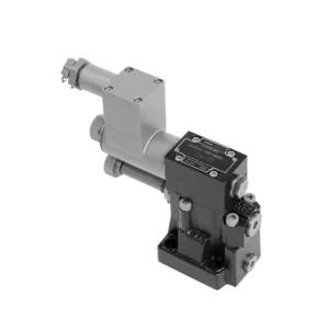
The G.DBW series pilot-operated explosion-proof pressure relief hydraulic valve is a cutting-edge hydraulic component specifically designed for applications in hazardous environments. With its exceptional explosion-proof features and reliable pressure relief capabilities, this valve ensures the utmost safety and performance in critical hydraulic systems.
The G.DBW series pilot-operated explosion-proof pressure relief hydraulic valve is the ultimate solution for ensuring safety and reliability in hazardous environments. With its explosion-proof design, reliable pressure relief capabilities, precise pressure control, and versatility, this valve delivers exceptional performance and protection in critical hydraulic systems; by following the recommended usage methods and maintenance practices, the G.DBW series valve guarantees longevity, safety, and optimal functionality. Upgrade your hydraulic system with the G.DBW series pilot-operated explosion-proof pressure relief hydraulic valve and experience unparalleled safety and reliability in hazardous environments.
G.DBW Series Pilot Operated Explosion-proof Pressure Relief Hydraulic Valve Key Characteristics:
- Взрывозащищенное исполнение:
- The G.DBW series valve is engineered with an explosion-proof design, making it suitable for use in environments where flammable gases or vapors are present.
- It meets rigorous safety standards and complies with industry regulations, reducing the risk of ignition or explosion in hazardous areas.
- Reliable Pressure Relief:
- This valve offers reliable pressure relief capabilities, protecting hydraulic systems from excessive pressure buildup.
- It automatically opens when the system pressure exceeds the set limit, diverting excess fluid to a low-pressure outlet and preventing potential damage or failures.
- Precise Pressure Control:
- The G.DBW series valve provides precise pressure control, allowing operators to set desired pressure levels within hydraulic systems.
- This feature ensures optimal system performance, protecting sensitive components and enhancing efficiency.
- Versatility and Customization:
- The valve is available in various sizes, pressure ratings, and configurations, accommodating various system requirements.
- It offers customization options for specific hydraulic applications, providing flexibility and adaptability.
G.DBW Series Pilot Operated Explosion-proof Pressure Relief Hydraulic Valve Parameter:
| Положение установки | Необязательный | ||||||
| Масса | G…DBW…10 | G…DBW…15 | G…DBW…20 | G…DBW…25 | G…DBW…30 | ||
| Base sub-plate mounting G…DBW | кг | about 5.6 | – | около 6,5 | – | около 7,9 | |
| threaded connection G…DBW..G.. | кг | около 7,9 | about 7.8 | about 7.7 | about 8.5 | about 8.4 | |
| Switching shock damping | кг | about 0.6 | |||||
| Technical parameters of directional valve | Refer to the solenoid valvetype G…WE6,normally close use G…3WE6A9, normally open use G…3WE6B9 | ||||||
| Жидкость | Минеральное масло, подходящее для уплотнений NBR и FKM | ||||||
| Фосфатный эфир для уплотнений FKM | |||||||
| Диапазон температур жидкости | ℃ | -30 до +80 (уплотнение NBR) | |||||
| -20 до +80 (уплотнение FKM) | |||||||
| Диапазон вязкости | мм2/с | от 10 до 800 | |||||
| Степень загрязнения | Максимально допустимая степень загрязнения жидкости: класс 9. NAS 1638 или 20/18/15, ISO4406 | ||||||
| Макс. рабочее давление | Port A, B, X, P | бар | 350 | ||||
| Port Y or T DBW | бар | 210 | |||||
| Макс. установочное давление | бар | 50; 100; 200; 315; 350 | |||||
| Мин. | бар | Interrelated with Q(Refer to the characteristic curve) | |||||
| NS (NG) | 10 | 15 | 20 | 25 | 30 | ||
| Макс. расход | Base Sub-plate mounting | л/мин | 250 | – | 500 | – | 650 |
| threaded connection | л/мин | 250 | 500 | 500 | 500 | 650 | |
G.DBW Series Pilot Operated Explosion-proof Pressure Relief Hydraulic Valve Advantages:
• Используется для монтажа нижней подкладки
• Installation face follow DIN 24340 E and ISO 6264
• Used in screw connection, Used for bottom sub-plate mounting
• Five pressure ranges
• Unloading operation via a built-on solenoid directional valv
• Два типа регулировки: ручка, регулировочный винт с защитным колпачком
• Optional switching shock damping
Usage Method Of G.DBW Series Pilot Operated Explosion-proof Pressure Relief Hydraulic Valve:
- Hazardous Environment Evaluation:
- Conduct a thorough evaluation of the hydraulic system’s operating environment to determine if it falls under hazardous classifications.
- Consider factors such as flammable gases, vapors, or combustible dust.
- Compliance and Certification:
- Ensure that the G.DBW series valve meets the necessary explosion-proof and safety standards for the specific hazardous environment.
- Verify compliance with regulatory bodies and obtain the appropriate certifications.
- Выбор клапана:
- Select the appropriate variant of the G.DBW series valve based on system specifications, including pressure requirements and flow capacity.
- Consider factors such as compatibility with other system components and the desired pressure relief setting.
- Установка:
- Follow the manufacturer’s instructions for properly installing the G.DBW series valve in the hydraulic system.
- Ensure secure connections, proper grounding, and adherence to safety guidelines.
Как работает гидравлический золотниковый клапан?
A hydraulic valve is a crucial component in hydraulic systems that controls the flow and direction of hydraulic fluid. It is responsible for regulating the pressure, allowing fluid to pass through, and directing it to various actuators or hydraulic components. The working principle of a hydraulic valve can be summarized as follows:
- Конструкция клапана:
- A hydraulic valve consists of a valve body, which houses the internal components, and a movable valve element, such as a spool or poppet.
- The valve body contains ports, passages, and chambers facilitating fluid flow.
- Управление потоком жидкости:
- When hydraulic fluid enters the valve through the inlet port, it encounters the valve element, determining the flow path.
- The valve element can be moved manually, mechanically, or through hydraulic pressure.
- Положения клапанов:
- Hydraulic valves have different positions, including open, closed, and partially open, which control the fluid flow.
- In the closed position, the valve blocks the flow of fluid entirely.
- In the open position, the valve allows fluid to flow freely through the specified ports.
- In the partially open position, the valve restricts or controls the flow rate of the fluid.
- Spool Valve Operation:
- In a spool valve, a cylindrical spool with lands or channels controls the fluid flow.
- By moving the spool within the valve body, different lands align with specific ports, enabling or blocking fluid flow.
- The movement of the spool is typically achieved using mechanical linkage, solenoids, or hydraulic pressure acting on the spool.
- Poppet Valve Operation:
- In a poppet valve, a movable poppet or disc seals or unseals the fluid flow passage.
- When the poppet is in the closed position, it rests against a seat, blocking fluid flow.
- To open the valve, the poppet is moved away from the seat, allowing fluid to flow through the passage.
- Механизмы управления:
- Hydraulic valves can be operated manually, mechanically, or through electrical means.
- Manual control involves levers, knobs, or handles to position the valve element manually.
- Mechanical control utilizes mechanical linkages or actuators to move the valve element.
- Electrical control employs solenoids or other electrically controlled devices to shift the valve element.
- Actuator Control:
- Hydraulic valves direct fluid to various hydraulic actuators, such as cylinders or motors.
- By opening or closing the appropriate valve ports, the hydraulic system can control the movement and operation of the actuators.
- System Stability and Safety:
- Hydraulic valves play a vital role in maintaining system stability and safety.
- Pressure relief valves, for example, protect the system from overpressure by diverting excess fluid to a low-pressure outlet.
Возможности и мощности завода:
(1) Сборка
Мы располагаем первоклассной независимой сборочной платформой для проведения исследований и разработок. Цех по производству гидравлических цилиндров имеет четыре полуавтоматические линии сборки подъемных цилиндров и одну автоматическую линию сборки цилиндров наклона с проектной годовой производственной мощностью 1 млн. штук. Цех по производству специальных цилиндров оснащен полуавтоматической очистной сборочной системой различных спецификаций с проектной годовой производственной мощностью 200 тыс. штук и оснащен известным обрабатывающим оборудованием с ЧПУ, обрабатывающим центром, высокоточным специальным оборудованием для обработки цилиндров, роботом-сварщиком, автоматической очистной машиной, автоматической сборочной машиной цилиндров и автоматической покрасочной производственной линией. Существующее критически важное оборудование насчитывает более 300 комплектов (комплектов). Оптимальное распределение и эффективное использование ресурсов оборудования позволяет обеспечить требования к точности изделий и удовлетворить потребности в высоком качестве продукции.


(2) Механическая обработка
Цех оснащен специализированным токарным центром с наклонной направляющей, обрабатывающим центром, высокоскоростным хонинговальным станком, сварочным роботом и другим сопутствующим оборудованием, которое позволяет обрабатывать цилиндрические трубы с максимальным внутренним диаметром 400 мм и максимальной длиной 6 м.

(3) Сварка

(4) Покраска и покрытие
С помощью небольших и средних цилиндрических автоматических линий нанесения лакокрасочных материалов на водной основе, обеспечивающих автоматическую загрузку и выгрузку роботом и автоматическое распыление, проектная производительность составляет 4000 изделий в смену;
У нас также имеется полуавтоматическая линия по производству краски для больших баллонов, приводимая в действие электроцепью, с проектной мощностью 60 ящиков в смену.


(5) Тестирование
У нас имеются первоклассные инспекционные центры и испытательные стенды, позволяющие гарантировать соответствие эксплуатационных характеристик цилиндра установленным требованиям.

Мы являемся одним из лучших производителей гидроцилиндров. Мы предлагаем широкий ассортимент гидроцилиндров. Мы также предлагаем сопутствующие товары. сельскохозяйственные редукторыМы экспортируем нашу продукцию клиентам по всему миру и заслужили хорошую репутацию благодаря превосходному качеству продукции и послепродажному обслуживанию. Мы приглашаем клиентов из Китая и других стран связаться с нами для деловых переговоров, обмена информацией и сотрудничать с нами!
Применение гидравлического цилиндра:
