

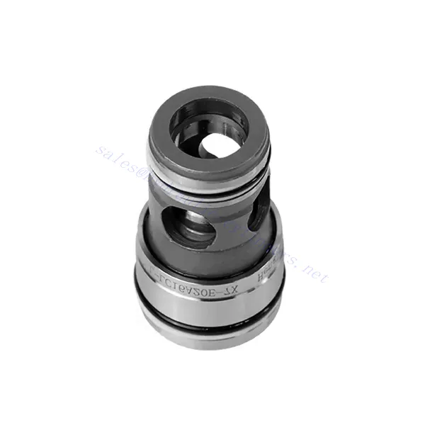
Гидравлический клапан с функцией регулирования давления серии L-LC

Гидравлический клапан управления давлением серии L-LC — это уникальный гидравлический компонент, предназначенный для точного регулирования давления в различных областях применения. Благодаря передовым функциям и прочной конструкции этот клапан обеспечивает оптимальную производительность и эффективность гидравлических систем.
Гидравлический клапан серии L-LC с функцией регулирования давления — это революционное решение для гидравлических систем, обеспечивающее точное управление давлением, универсальность и долговечность. Следуя рекомендациям по эксплуатации и техническому обслуживанию, вы сможете раскрыть весь потенциал клапана серии L-LC и добиться улучшенного контроля, безопасности и эффективности гидравлических систем. Модернизируйте свою гидравлическую систему уже сегодня и воспользуйтесь преимуществами точности и контроля с помощью гидравлического клапана серии L-LC с функцией регулирования давления.
Основные характеристики гидравлического клапана управления давлением серии L-LC:
- Функция контроля давления:
- Клапан серии L-LC оснащен сложной функцией контроля давления, позволяющей точно регулировать гидравлическое давление в системе.
- Эта характеристика обеспечивает постоянное и надежное управление давлением, повышая производительность системы, безопасность и снижая потребление энергии.
- Универсальные варианты конфигурации:
- Этот клапан доступен в различных конфигурациях, включая 2-ходовой и 3-ходовой варианты, что обеспечивает совместимость с различными требованиями гидравлических систем.
- Двухходовая конфигурация облегчает управление давлением включения/выключения, тогда как трехходовая конструкция позволяет реализовать более сложные функции управления, такие как сброс давления или байпас.
- Высококачественное строительство:
- Клапаны серии L-LC тщательно спроектированы с использованием высококачественных материалов и прецизионных технологий производства, что обеспечивает их прочность и долговечность.
- Прочная конструкция позволяет ему выдерживать суровые условия эксплуатации, включая высокое давление, перепады температур и воздействие загрязняющих веществ.
- Быстрое время отклика:
- Этот клапан может похвастаться впечатляющим временем срабатывания, что позволяет быстро регулировать изменения давления в гидравлической системе.
- Быстрое время отклика обеспечивает быстрое и точное управление, оптимизируя производительность системы и сводя к минимуму риск колебаний давления.
Параметры гидравлического клапана управления давлением серии L-LC:
| Технические данные | ||||||||
| Жидкость | Минеральное масло, подходящее для уплотнений NBR и FKM | |||||||
| Фосфатный эфир для уплотнений FKM | ||||||||
| Диапазон температур жидкости | ℃ | -30 до +80 (уплотнение NBR) | ||||||
| -20 до +80 (уплотнение FKM) | ||||||||
| Диапазон вязкости | мм2/с | 2,8–380 | ||||||
| Степень загрязнения | Максимально допустимая степень загрязнения жидкости: класс 9. NAS 1638 или 20/18/15, ISO4406 | |||||||
| Двухходовые картриджные клапаны | ||||||||
| Макс. рабочее давление - порты A и B | бар | 420 | ||||||
| Макс. расход (рекомендация) | Размер | 16 | 25 | 32 | 40 | 50 | 63 | |
| Poppet valve cartridge “E”and”A” | л/мин | 300 | 450 | 600 | 1000 | 1600 | 2500 | |
| Spool valve cartridge “D”and”B” | л/мин | 175 | 300 | 450 | 700 | 1400 | 1750 | |
Преимущества гидравлического клапана с функцией регулирования давления серии L-LC:
• Дополнительная крышка управления регулировкой давления и интеграция других функций
• Доступны несколько уровней давления
Метод использования гидравлического клапана с функцией регулирования давления серии L-LC:
- Оценка системы:
- Оцените вашу гидравлическую систему и определите конкретные требования к контролю давления.
- Определите, подходит ли клапан серии L-LC для вашей системы, исходя из диапазона давления, расхода и совместимости с вашим применением.
- Выбор клапана:
- Выберите подходящий вариант клапана серии L-LC в зависимости от параметров вашей системы и потребностей в регулировании давления.
- Примите во внимание номинальное давление, пропускную способность, время срабатывания и совместимость с вашим конкретным применением.
- Установка:
- Follow the manufacturer’s installation instructions carefully to ensure proper alignment and secure valve mounting.
- Используйте совместимые гидравлические фитинги, адаптеры и уплотнения для обеспечения герметичности соединений. Затягивайте соединения надлежащим образом, избегая чрезмерной затяжки, которая может повредить клапан или фитинги.
- Калибровка давления:
- Откалибруйте клапан серии L-LC на нужный диапазон давления, используя соответствующее оборудование для измерения давления и регулировочные механизмы.
- Follow the manufacturer’s guidelines for pressure calibration procedures and ensure that the valve operates within the specified pressure limits.
Как установить гидравлический клапан регулирования расхода?
Чтобы установить гидравлический клапан управления потоком, следуйте этим пошаговым инструкциям:
- Определите клапан: Определите, какой тип гидравлического клапана-регулятора расхода вы используете. Доступны различные типы, включая игольчатые клапаны, дроссельные клапаны и регулируемые клапаны-регуляторы расхода. Убедитесь, что клапан подходит для вашей области применения и совместим с вашей гидравлической системой.
- Соберите необходимые инструменты и материалы: Collect the necessary tools and materials, including appropriate hydraulic fittings, adapters, hoses, wrenches, and Teflon tape (thread sealant). Refer to the manufacturer’s instructions for any specific tools or components needed.
- Подготовьте гидравлическую систему: Отключите гидравлическую систему и сбросьте давление, активировав предохранительный клапан или втянув гидроцилиндры. Этот шаг крайне важен для безопасности и предотвращает случайное движение или выброс гидравлической жидкости.
- Определите направление потока: Определите направление потока в вашей гидравлической системе. Обычно направление потока указано стрелками на гидравлических компонентах. Прежде чем продолжить, убедитесь, что вы понимаете правильное направление потока.
- Определите точку установки: Определите оптимальное место для установки клапана управления потоком в вашей гидравлической системе. Учитывайте такие факторы, как доступность, близость к приводу или гидравлическому компоненту, а также простота эксплуатации. Убедитесь, что имеется достаточно места для надежной установки клапана.
- Установите клапан: Securely mount the hydraulic flow control valve in the chosen location using appropriate brackets or clamps. Ensure the valve is positioned correctly, aligning the inlet and outlet ports with the flow direction. Follow the manufacturer’s instructions for the specific mounting requirements of your valve.
- Подключите входной и выходной порты: Подсоедините гидравлические шланги или трубки к впускному и выпускному отверстиям клапана управления потоком. Используйте подходящие гидравлические фитинги и адаптеры для обеспечения герметичного соединения. Нанесите тефлоновую ленту или резьбовой герметик на наружную резьбу фитингов для обеспечения надёжного и герметичного соединения. Затяните соединения ключами, чтобы избежать утечек, но не перетягивайте.
- Отрегулируйте скорость потока: Depending on the type of flow control valve, you may need to adjust the flow rate. Some valves have adjustable knobs or screws that allow you to fine-tune the flow rate. Follow the manufacturer’s instructions to set the desired flow rate.
- Протестируйте систему: После установки клапана управления гидравлическим потоком медленно восстановите давление в гидравлической системе. Проверьте систему, чтобы убедиться в правильности работы клапана. Наблюдайте за расходом и убедитесь, что клапан регулирует поток должным образом. Внесите необходимые изменения для достижения желаемого расхода.
- Мониторинг и обслуживание: Regularly inspect the hydraulic flow control valve for any signs of leakage, damage, or reduced performance. Clean the valve and surrounding area to remove dirt and debris that may affect its operation. Follow the manufacturer’s recommended maintenance schedule and guidelines to ensure optimal performance and longevity.
Возможности и мощности завода:
(1) Сборка
Мы располагаем первоклассной независимой сборочной платформой для проведения исследований и разработок. Цех по производству гидравлических цилиндров имеет четыре полуавтоматические линии сборки подъемных цилиндров и одну автоматическую линию сборки цилиндров наклона с проектной годовой производственной мощностью 1 млн. штук. Цех по производству специальных цилиндров оснащен полуавтоматической очистной сборочной системой различных спецификаций с проектной годовой производственной мощностью 200 тыс. штук и оснащен известным обрабатывающим оборудованием с ЧПУ, обрабатывающим центром, высокоточным специальным оборудованием для обработки цилиндров, роботом-сварщиком, автоматической очистной машиной, автоматической сборочной машиной цилиндров и автоматической покрасочной производственной линией. Существующее критически важное оборудование насчитывает более 300 комплектов (комплектов). Оптимальное распределение и эффективное использование ресурсов оборудования позволяет обеспечить требования к точности изделий и удовлетворить потребности в высоком качестве продукции.


(2) Механическая обработка
Цех оснащен специализированным токарным центром с наклонной направляющей, обрабатывающим центром, высокоскоростным хонинговальным станком, сварочным роботом и другим сопутствующим оборудованием, которое позволяет обрабатывать цилиндрические трубы с максимальным внутренним диаметром 400 мм и максимальной длиной 6 м.


(3) Сварка


(4) Покраска и покрытие
С помощью небольших и средних цилиндрических автоматических линий нанесения лакокрасочных материалов на водной основе, обеспечивающих автоматическую загрузку и выгрузку роботом и автоматическое распыление, проектная производительность составляет 4000 изделий в смену;
У нас также имеется полуавтоматическая линия по производству краски для больших баллонов, приводимая в действие электроцепью, с проектной мощностью 60 ящиков в смену.


(5) Тестирование
У нас имеются первоклассные инспекционные центры и испытательные стенды, позволяющие гарантировать соответствие эксплуатационных характеристик цилиндра установленным требованиям.


Мы являемся одним из лучших производителей гидроцилиндров. Мы предлагаем широкий ассортимент гидроцилиндров. Мы также предлагаем сопутствующие товары. сельскохозяйственные редукторыМы экспортируем нашу продукцию клиентам по всему миру и заслужили хорошую репутацию благодаря превосходному качеству продукции и послепродажному обслуживанию. Мы приглашаем клиентов из Китая и других стран связаться с нами для деловых переговоров, обмена информацией и сотрудничать с нами!