M-SR Series Check Hydraulic Valve Cartridge
Являясь одним из производителей, поставщиков и экспортеров механической продукции, мы предлагаем гидравлические цилиндры и многие другие изделия.
Пожалуйста, свяжитесь с нами для получения подробной информации.
Почта:sales@hydraulic-cylinders.net
Производитель поставщик экспортер гидроцилиндров.
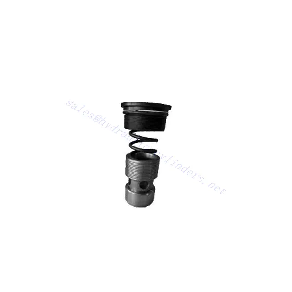
M-SR Series Check Hydraulic Valve Cartridge
The M-SR series check hydraulic valve cartridge is versatile and essential in hydraulic systems. This valve cartridge is designed to regulate fluid flow and prevent backflow and offers reliable performance, durability, and ease of installation.
The M-SR series check hydraulic valve cartridge is a reliable and efficient solution for fluid control in hydraulic systems. With efficient check valve functionality, compact design, high flow capacity, and robust construction, this valve cartridge ensures optimal system performance, prevents backflow, and enhances overall efficiency. By following the recommended usage methods and maintenance practices, the M-SR series check hydraulic valve cartridge delivers reliable operation and extends the lifespan of hydraulic systems. Upgrade your hydraulic system with the m-sr series check hydraulic valve cartridge and experience efficient and reliable fluid control.
M-SR Series Check Hydraulic Valve Cartridge Key Characteristics:
- Эффективная работа обратного клапана:
- The M-SR series valve cartridge features a built-in check valve mechanism that enables the unidirectional flow of hydraulic fluid.
- It effectively prevents backflow and ensures fluid flows in the desired direction, minimizing the risk of system damage and inefficiency.
- Компактная и универсальная конструкция:
- The valve cartridge is compact, making it suitable for applications with limited space or where weight considerations are crucial.
- Its versatile design allows easy integration into various hydraulic systems, including mobile machinery, industrial equipment, and hydraulic power units.
- Высокая пропускная способность:
- Despite its compact size, the M-SR series valve cartridge offers high flow capacity, allowing for efficient fluid transfer and system performance.
- It minimizes pressure drops, ensuring optimal hydraulic power delivery to actuators and other components.
- Надежная конструкция:
- Constructed from high-quality materials, the M-SR series valve cartridge demonstrates excellent durability and resistance to wear and corrosion.
- It is designed to withstand demanding operating conditions, prolonging the valve cartridge’s lifespan and reducing maintenance requirements.
M-SR Series Check Hydraulic Valve Cartridge Parameter:
| Технические характеристики | бар | NG6-30 | |||||
| Макс. рабочее давление | бар | 315 | |||||
| Давление трещины | бар | Обратитесь к характеристической кривой. | |||||
| Макс. расход | л/мин | Обратитесь к характеристической кривой. | |||||
| Диапазон вязкости | мм2/с | 2,8–380 | |||||
| Диапазон температур жидкости | ℃ | -30 to +80(NBR seals) | |||||
| -20 to +80(FKM seals) | |||||||
| Жидкость | Минеральное масло, подходящее для уплотнений NBR и FKM | ||||||
| Фосфатный эфир для уплотнений FKM | |||||||
| Степень загрязнения | Максимально допустимая степень загрязнения жидкости: класс 9. NAS 1638 или 20/18/15, ISO4406 | ||||||
| Размер | 8 | 10 | 15 | 20 | 25 | 30 | |
| Weight: Right angled check valve cartridge | кг | 0.03 | 0.05 | 0.08 | 0.14 | 0.32 | 0.47 |
M-SR Series Check Hydraulic Valve Cartridge Advantages:
NG6-30
• Используется при установке блока масляного тракта
• Leak-free closure
• Various opening pressures available (see model description)
Usage Method Of M-SR Series Check Hydraulic Valve Cartridge:
- Системный анализ:
- Before installation, thoroughly analyze the hydraulic system to determine the specific requirements and operational parameters.
- Consider factors such as flow rates, pressure ratings, and compatibility with the M-SR series valve cartridge.
- Выбор клапана:
- Select the appropriate M-SR series valve cartridge variant based on the system requirements and specifications.
- Примите во внимание такие факторы, как пропускная способность, номинальное давление и совместимость с другими компонентами системы.
- Установка:
- Follow the manufacturer’s instructions for properly installing the M-SR series valve cartridge in the hydraulic system.
- Ensure a secure fit within the valve cavity, proper alignment with the fluid flow path, and appropriate sealing to prevent leaks.
- Направление потока жидкости:
- Ensure the M-SR Series Valve Cartridge is installed in the correct orientation, allowing for the desired fluid flow direction.
- Совместите картридж клапана с потоком системы, обеспечив правильное зацепление механизма обратного клапана.
How Does A Hydraulic Diverter Valve Work?
A hydraulic diverter valve is a key component in hydraulic systems that allows the operator to redirect hydraulic fluid flow from one path to another. It provides flexibility in controlling the flow direction and enables the use of multiple hydraulic actuators with a single hydraulic power source. Here’s a breakdown of how a hydraulic diverter valve works:
- Конструкция клапана:
- A hydraulic diverter valve typically consists of a valve body with multiple ports, a movable spool or ball, and actuators such as levers, solenoids, or pilot pressure mechanisms.
- The valve body contains internal passages and chambers that direct the flow of hydraulic fluid.
- Пути потока жидкости:
- The diverter valve has multiple ports that connect to different hydraulic components in the system, such as the pump, reservoir, actuators, and other valves.
- These ports include an inlet port, outlet ports, and work ports, each serving a specific purpose in controlling the fluid flow.
- Spool or Ball:
- The valve body houses a movable spool or ball that controls the flow of hydraulic fluid.
- The spool can slide within the valve body, while the ball can rotate or move linearly to open or close specific passages.
- Actuation Mechanisms:
- Hydraulic diverter valves can be actuated manually, electrically, or hydraulically, depending on the specific design and application requirement.
- Manual actuation involves levers or handles that the operator physically moves to position the spool or ball.
- Electrical actuation utilizes solenoids that receive electrical signals to shift the spool or ball, allowing for remote control and automation.
- Hydraulic actuation employs pilot pressure to move the spool or ball, often in conjunction with electrical or manual control.
- Положения клапанов:
- Depending on the valve design, there are typically multiple positions that the spool or ball can assume, each corresponding to a specific flow path.
- Common positions include neutral, where all ports are blocked, and various actuating positions that allow flow between specific ports.
- As the spool or ball shifts, it aligns with specific ports, opening or closing passages and directing the hydraulic fluid accordingly.
- Operator Input:
- The operator engages the hydraulic diverter valve by actuating the manual lever, applying electrical signals to solenoids, or manipulating pilot pressure.
- This input determines the desired valve position, which in turn determines the flow direction and the action of the hydraulic actuators.
- Работа системы:
- Once the hydraulic diverter valve is in the desired position, hydraulic fluid flows through the appropriate passages and ports.
- This flow of fluid can be directed to different hydraulic actuators, allowing for selective control of the actuator’s movement or operation.
Возможности и мощности завода:
(1) Сборка
Мы располагаем первоклассной независимой сборочной платформой для проведения исследований и разработок. Цех по производству гидравлических цилиндров имеет четыре полуавтоматические линии сборки подъемных цилиндров и одну автоматическую линию сборки цилиндров наклона с проектной годовой производственной мощностью 1 млн. штук. Цех по производству специальных цилиндров оснащен полуавтоматической очистной сборочной системой различных спецификаций с проектной годовой производственной мощностью 200 тыс. штук и оснащен известным обрабатывающим оборудованием с ЧПУ, обрабатывающим центром, высокоточным специальным оборудованием для обработки цилиндров, роботом-сварщиком, автоматической очистной машиной, автоматической сборочной машиной цилиндров и автоматической покрасочной производственной линией. Существующее критически важное оборудование насчитывает более 300 комплектов (комплектов). Оптимальное распределение и эффективное использование ресурсов оборудования позволяет обеспечить требования к точности изделий и удовлетворить потребности в высоком качестве продукции.


(2) Механическая обработка
Цех оснащен специализированным токарным центром с наклонной направляющей, обрабатывающим центром, высокоскоростным хонинговальным станком, сварочным роботом и другим сопутствующим оборудованием, которое позволяет обрабатывать цилиндрические трубы с максимальным внутренним диаметром 400 мм и максимальной длиной 6 м.

(3) Сварка

(4) Покраска и покрытие
С помощью небольших и средних цилиндрических автоматических линий нанесения лакокрасочных материалов на водной основе, обеспечивающих автоматическую загрузку и выгрузку роботом и автоматическое распыление, проектная производительность составляет 4000 изделий в смену;
У нас также имеется полуавтоматическая линия по производству краски для больших баллонов, приводимая в действие электроцепью, с проектной мощностью 60 ящиков в смену.


(5) Тестирование
У нас имеются первоклассные инспекционные центры и испытательные стенды, позволяющие гарантировать соответствие эксплуатационных характеристик цилиндра установленным требованиям.

Мы являемся одним из лучших производителей гидроцилиндров. Мы предлагаем широкий ассортимент гидроцилиндров. Мы также предлагаем сопутствующие товары. сельскохозяйственные редукторыМы экспортируем нашу продукцию клиентам по всему миру и заслужили хорошую репутацию благодаря превосходному качеству продукции и послепродажному обслуживанию. Мы приглашаем клиентов из Китая и других стран связаться с нами для деловых переговоров, обмена информацией и сотрудничать с нами!
Применение гидравлического цилиндра:
