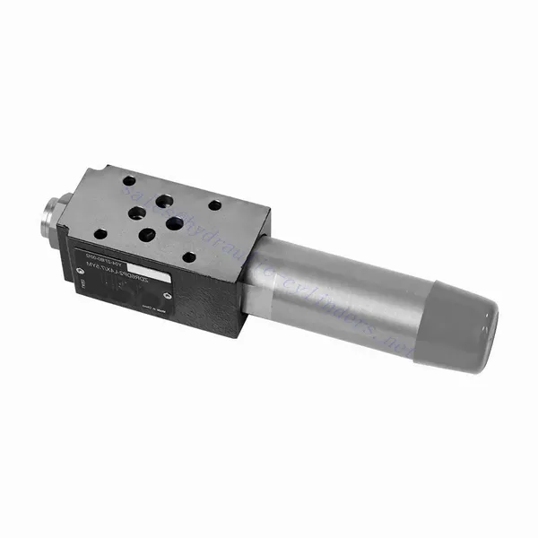
Гидравлический редукционный клапан прямого действия серии ZDR
Являясь одним из производителей, поставщиков и экспортеров механической продукции, мы предлагаем гидравлические цилиндры и многие другие изделия.
Пожалуйста, свяжитесь с нами для получения подробной информации.
Почта:sales@hydraulic-cylinders.net
Производитель поставщик экспортер гидроцилиндров.
Гидравлический редукционный клапан прямого действия серии ZDR
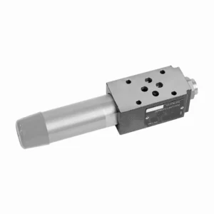
Редукционный клапан прямого действия серии ZDR — высокоэффективный и надежный компонент, обеспечивающий точное регулирование давления в гидравлических системах. Благодаря конструкции прямого действия и исключительным рабочим характеристикам этот клапан обеспечивает точное снижение давления в соответствии с конкретными требованиями системы.
Редукционный клапан прямого действия серии ZDR — это высокопроизводительное решение для точного регулирования давления в гидравлических системах. Благодаря конструкции прямого действия, точному регулированию давления, широкому диапазону давления и высокой пропускной способности этот клапан обеспечивает эффективное и надежное снижение давления, защищая компоненты системы. При соблюдении рекомендуемых методов эксплуатации и технического обслуживания клапан серии ZDR обеспечивает надежную работу, продлевая срок службы гидравлических систем. Модернизируйте свою гидравлическую систему, установив редукционный клапан прямого действия серии ZDR, и вы сможете добиться оптимального регулирования давления, повышая эффективность и производительность системы.
Основные характеристики гидравлического редукционного клапана прямого действия серии ZDR:
- Конструкция прямого действия:
- Клапан серии ZDR имеет конструкцию прямого действия, что позволяет ему обеспечивать точный контроль давления без необходимости использования внешних управляющих контуров.
- Такая конструкция упрощает монтаж и снижает сложность гидравлических систем.
- Точный контроль давления:
- Этот клапан обеспечивает исключительную точность регулирования давления, позволяя гидравлическим системам поддерживать желаемый диапазон давления с высокой надежностью.
- Обеспечивает стабильную работу и защищает чувствительные компоненты системы от чрезмерного давления.
- Широкий диапазон давления:
- Клапан серии ZDR доступен в различных диапазонах давления, что делает его пригодным для разнообразных гидравлических применений.
- Гибкость диапазона давления позволяет настраивать систему в соответствии с конкретными требованиями и оптимизировать производительность.
- Высокая пропускная способность:
- Этот клапан обладает превосходной пропускной способностью, что позволяет ему выдерживать высокие скорости потока, сохраняя при этом точный контроль давления.
- Он обеспечивает эффективное регулирование жидкости и бесперебойную работу системы даже в сложных условиях.
Параметры гидравлического редукционного клапана прямого действия серии ZDR:
| Технические характеристики | НГ10 | НГ16 | ||
| Жидкость | Минеральное масло, подходящее для уплотнений NBR и FKM | |||
| Фосфатный эфир для уплотнений FKM | ||||
| Диапазон температур жидкости | ℃ | -30 до +80 (уплотнения NBR) | ||
| -20 до +80 (уплотнители FKM) | ||||
| Диапазон вязкости | мм2/с | от 10 до 800 | ||
| Степень загрязнения | Максимально допустимая степень загрязнения жидкости: класс 9. NAS 1638 или 20/18/15, ISO4406 | |||
| Номинальное давление | бар | 315 | ||
| Макс. рабочее давление | Порт П | бар | 315 | |
| Макс. рабочее давление | Порт А | бар | 315 | 250 |
| Макс. рабочее давление | Порт Y | бар | Отдельно и под нулевым давлением относительно бака | |
| Давление установки | Мин. | бар | Зависит от расхода (см. кривые) | |
| Макс. | бар | 50; 100; 200; 315 | 50; 100; 200; 250 | |
| Макс. расход | л/мин | 120 | 220 | |
| Масса | кг | около 6,5 | около 8,8 | |
Преимущества гидравлического редукционного клапана прямого действия серии ZDR:
• Структура типа сэндвич
• Монтажная поверхность соответствует стандартам DIN 24340 A и ISO 4401
• Четыре диапазона давления
• Два типа регулировки: ручка, регулировочный винт с защитным колпачком
• С интерфейсом манометра
• Дополнительный однонаправленный клапан
Метод использования гидравлического редукционного клапана прямого действия серии ZDR:
- Системный анализ:
- Проведите тщательный анализ гидравлической системы, чтобы определить конкретные требования к контролю давления.
- Учитывайте максимальное рабочее давление, желаемый диапазон давления и расход.
- Выбор клапана:
- Выберите подходящий вариант клапана серии ZDR на основе характеристик регулирования давления в системе.
- Примите во внимание номинальное давление, пропускную способность и совместимость с другими компонентами системы.
- Установка:
- Следуйте инструкциям производителя для правильной установки редукционного клапана прямого действия серии ZDR в гидравлическую систему.
- Обеспечьте правильное выравнивание и надежные соединения, чтобы предотвратить утечки и оптимизировать производительность.
- Калибровка:
- Откалибруйте клапан, чтобы установить желаемое давление на выходе.
- Используйте манометры или другие измерительные приборы для точной регулировки клапана и оптимального контроля давления.
Как работает гидравлический селекторный клапан?
Гидравлический селекторный клапан, также известный как гидравлический распределительный клапан или гидравлический регулирующий клапан, — это устройство, используемое для направления потока гидравлической жидкости в гидравлической системе. Он позволяет оператору управлять направлением потока жидкости, выбирая различные гидравлические контуры или компоненты для управления. Ниже приведено описание принципа работы гидравлического селекторного клапана:
- Конструкция клапана:
- Гидравлический селекторный клапан состоит из корпуса с несколькими портами и внутренними каналами.
- Обычно он имеет исполнительный механизм, такой как рычаг или соленоид, для управления движением золотника или тарелки клапана.
- Конфигурация порта:
- Селекторный клапан имеет несколько портов, обычно обозначенных как A, B и C или иногда называемых P, T и A/B/C.
- Порт P (давление) подключается к гидравлическому насосу или стороне высокого давления системы.
- Порт T (бак) подключается к гидравлическому резервуару или стороне низкого давления системы.
- Порты A, B и C — это выходные порты, которые подключаются к различным гидравлическим контурам или компонентам.
- Положения клапанов:
- Селекторный клапан имеет различные положения, которые определяют путь потока гидравлической жидкости.
- Обычные позиции включают «A», «B», «C», «AB», «AC» и «BC» в зависимости от конкретной конструкции клапана.
- Управление потоком жидкости:
- Когда клапан находится в нейтральном или стандартном положении, обычно обозначенном «N», поток жидкости блокируется, и поток между портами отсутствует.
- Когда оператор приводит в действие клапан, перемещая рычаг или подавая питание на соленоид, золотник или тарелка клапана перемещается в другое положение, обеспечивая поток жидкости.
- Выбор пути потока:
- Перемещая исполнительный механизм, оператор может выбрать желаемый путь потока.
- Например, когда клапан находится в положении «А», жидкость перетекает из порта P в порт A, позволяя гидравлическому контуру или компоненту, подключенному к порту A, работать.
- Несколько путей потока:
- В зависимости от конкретной конструкции клапана гидравлический селекторный клапан может обеспечивать несколько путей потока.
- Например, в положении «AB» жидкость может течь из порта P в оба порта A и B одновременно, что позволяет работать двум отдельным гидравлическим контурам или компонентам.
- Управление и эксплуатация:
- Исполнительный механизм селекторного клапана может быть ручным, когда оператор физически перемещает рычаг или ручку, или электрическим или пневматическим, использующим соленоиды или другие устройства управления.
- Электроуправляемые селекторные клапаны могут быть интегрированы в автоматизированные системы или управляться дистанционно.
- Гибкость системы:
- Гидравлические селекторные клапаны обеспечивают гибкость в проектировании и эксплуатации системы.
- Они позволяют оператору переключаться между различными гидравлическими контурами или компонентами, облегчая такие задачи, как позиционирование оборудования, управление навесным оборудованием или переключение между различными орудиями.
Возможности и мощности завода:
(1) Сборка
Мы располагаем первоклассной независимой сборочной платформой для проведения исследований и разработок. Цех по производству гидравлических цилиндров имеет четыре полуавтоматические линии сборки подъемных цилиндров и одну автоматическую линию сборки цилиндров наклона с проектной годовой производственной мощностью 1 млн. штук. Цех по производству специальных цилиндров оснащен полуавтоматической очистной сборочной системой различных спецификаций с проектной годовой производственной мощностью 200 тыс. штук и оснащен известным обрабатывающим оборудованием с ЧПУ, обрабатывающим центром, высокоточным специальным оборудованием для обработки цилиндров, роботом-сварщиком, автоматической очистной машиной, автоматической сборочной машиной цилиндров и автоматической покрасочной производственной линией. Существующее критически важное оборудование насчитывает более 300 комплектов (комплектов). Оптимальное распределение и эффективное использование ресурсов оборудования позволяет обеспечить требования к точности изделий и удовлетворить потребности в высоком качестве продукции.


(2) Механическая обработка
Цех оснащен специализированным токарным центром с наклонной направляющей, обрабатывающим центром, высокоскоростным хонинговальным станком, сварочным роботом и другим сопутствующим оборудованием, которое позволяет обрабатывать цилиндрические трубы с максимальным внутренним диаметром 400 мм и максимальной длиной 6 м.

(3) Сварка

(4) Покраска и покрытие
С помощью небольших и средних цилиндрических автоматических линий нанесения лакокрасочных материалов на водной основе, обеспечивающих автоматическую загрузку и выгрузку роботом и автоматическое распыление, проектная производительность составляет 4000 изделий в смену;
У нас также имеется полуавтоматическая линия по производству краски для больших баллонов, приводимая в действие электроцепью, с проектной мощностью 60 ящиков в смену.


(5) Тестирование
У нас имеются первоклассные инспекционные центры и испытательные стенды, позволяющие гарантировать соответствие эксплуатационных характеристик цилиндра установленным требованиям.

Мы являемся одним из лучших производителей гидроцилиндров. Мы предлагаем широкий ассортимент гидроцилиндров. Мы также предлагаем сопутствующие товары. сельскохозяйственные редукторыМы экспортируем нашу продукцию клиентам по всему миру и заслужили хорошую репутацию благодаря превосходному качеству продукции и послепродажному обслуживанию. Мы приглашаем клиентов из Китая и других стран связаться с нами для деловых переговоров, обмена информацией и сотрудничать с нами!
Применение гидравлического цилиндра:
