

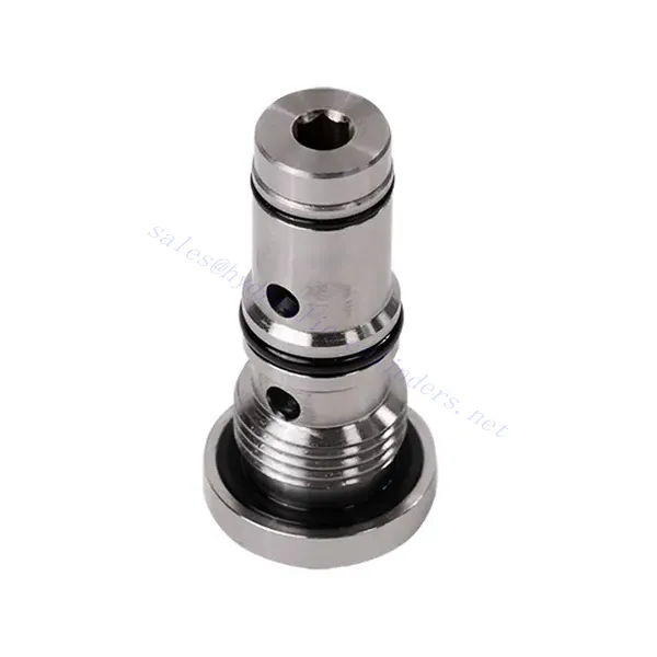
Челночный гидравлический клапан серии KSF
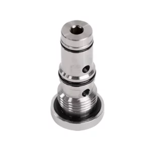

Челночный гидравлический клапан серии KSF — это высокопроизводительный компонент, предназначенный для улучшения управления потоком жидкости в гидравлических системах. Благодаря усовершенствованной и прочной конструкции этот клапан обеспечивает точную и надежную работу, гарантируя оптимальную производительность системы.
Челночный гидроклапан серии KSF — это превосходное решение для управления потоком жидкости в гидравлических системах. Благодаря функциональности челночного клапана, прочной конструкции, высокой пропускной способности и компактному исполнению этот клапан оптимизирует производительность и обеспечивает эффективное использование гидравлической мощности. При соблюдении рекомендуемых методов эксплуатации и технического обслуживания челночный гидроклапан серии KSF обеспечивает надежную работу и продлевает срок службы гидравлических систем. Модернизируйте свою гидравлическую систему с помощью челночного гидроклапана серии KSF и ощутите улучшенное управление потоком жидкости, повышая общую производительность системы.
Основные характеристики челночного гидравлического клапана серии KSF:
- Функциональность челночного клапана:
- Клапан серии KSF имеет конструкцию челночного клапана для перенаправления потока гидравлической жидкости между двумя контурами.
- Позволяет выбрать контур с более высоким давлением, обеспечивая эффективное использование гидравлической мощности и предотвращая дисбаланс давления.
- Надежная конструкция:
- Изготовленный из прочных материалов, челночный гидравлический клапан серии KSF предназначен для работы в условиях высокого давления и сложных условиях эксплуатации.
- Прочная конструкция обеспечивает долговечность и надежность, сводя к минимуму время простоя и затраты на техническое обслуживание.
- Высокая пропускная способность:
- Клапан серии KSF обеспечивает высокую пропускную способность, что позволяет эффективно перекачивать гидравлическую жидкость между контурами.
- Он сводит к минимуму перепады давления, обеспечивая максимальную подачу мощности и производительность системы.
- Компактная и универсальная конструкция:
- The valve’s compact design makes it suitable for installations with limited space or weight constraints.
- Его универсальность позволяет легко интегрировать его в различные гидравлические системы, включая промышленное оборудование, мобильную технику и силовые агрегаты.
Параметры челночного гидравлического клапана серии KSF:
| Размер | NG6 | НГ10 | |
| Диапазон температур жидкости | ℃ | -30 до +80 (уплотнения NBR) | |
| -20 до +80 (уплотнители FKM) | |||
| Диапазон вязкости | мм2/с | Рекомендация 30–80, разрешение 20–380. | |
| Макс. рабочее давление | бар | 350 | |
| Макс. расход | л/мин | 40 | 60 |
| Масса | кг | 0.5 | 0.8 |
| Жидкость | Минеральное масло, подходящее для уплотнений NBR и FKM | ||
| Фосфатный эфир для уплотнений FKM | |||
| Степень загрязнения | Максимально допустимая степень загрязнения жидкости: класс 9. NAS 1638 или 20/18/15, ISO4406 | ||
Преимущества челночного гидравлического клапана серии KSF:
• Герметичность без утечек
• Картриджная конструкция для установки масляного блока
Метод использования челночного гидравлического клапана серии KSF:
- Системный анализ:
- Перед установкой проведите комплексный анализ гидравлической системы, чтобы определить конкретные требования и рабочие параметры.
- Примите во внимание такие факторы, как скорость потока, номинальное давление и совместимость с челночным гидравлическим клапаном серии KSF.
- Выбор клапана:
- Choose the appropriate KSF series valve variant based on the system’s requirements and specifications.
- Примите во внимание такие факторы, как пропускная способность, номинальное давление и совместимость с другими компонентами системы.
- Установка:
- Follow the manufacturer’s instructions for properly installing the KSF series shuttle hydraulic Valve in the hydraulic system.
- Обеспечьте надежную фиксацию, правильное совмещение с траекторией потока жидкости и надлежащую герметизацию для предотвращения утечек.
- Подключение цепи:
- Подключите впускные и выпускные отверстия клапана к соответствующим контурам, требующим отвода жидкости.
- Обеспечьте правильную идентификацию и подключение контура высокого давления и контура низкого давления.
Как работает гидравлический клапан управления потоком?
A hydraulic flow control valve is a device used to regulate and control the speed of hydraulic fluid within a hydraulic system. It allows the operator to adjust the flow rate of the liquid, thereby preventing the speed of hydraulic actuators or controlling the rate of energy transfer. Here’s an explanation of how a hydraulic flow control valve works:
- Конструкция клапана:
- Гидравлический клапан управления потоком обычно состоит из корпуса клапана с впускным и выпускным отверстиями, подвижной катушки или тарелки и исполнительного механизма.
- Корпус клапана содержит внутренние каналы и камеры, которые управляют потоком гидравлической жидкости.
- Пути потока жидкости:
- Клапан управления потоком имеет впускное отверстие, которое подключается к гидравлическому источнику энергии, например, насосу, и выпускное отверстие, которое подключается к гидравлическому приводу или другому компоненту.
- Клапан обеспечивает различные пути потока жидкости, позволяя контролировать и регулировать его.
- Катушка или тарелка:
- В корпусе клапана находится подвижная катушка или тарелка, которая регулирует поток гидравлической жидкости.
- Катушка может скользить внутри корпуса клапана, в то время как тарелка может перемещаться линейно или вращаться, открывая или закрывая определенные каналы.
- Исполнительный механизм:
- Гидравлические клапаны регулирования расхода могут приводиться в действие вручную, электрически или другими способами в зависимости от конкретных требований конструкции и области применения.
- Ручное приведение в действие подразумевает регулировку рукоятки, ручки или рычага для установки катушки или тарелки в нужное положение.
- В электрическом приводе используются соленоиды, которые получают электрические сигналы для перемещения катушки или тарелки, что позволяет осуществлять дистанционное управление и автоматизацию.
- Положения клапанов:
- Гидравлический клапан управления потоком обычно имеет несколько положений, которые может принимать золотник или тарелка, каждое из которых соответствует определенному расходу.
- Клапан может иметь ряд предустановленных положений или обеспечивать плавную регулировку для точной настройки расхода.
- При перемещении золотника или тарелки он совмещается с определенными каналами, открывая или закрывая их, чтобы контролировать поток жидкости.
- Регулирование потока:
- Изменяя положение золотника или тарелки, оператор может контролировать размер проточных каналов, тем самым регулируя расход гидравлической жидкости.
- Когда проходы полностью открыты, жидкость течет свободно, обеспечивая максимальную скорость потока.
- Частичное перекрытие проходов ограничивает поток, уменьшая его скорость и контролируя скорость гидравлических приводов.
- Компенсация давления:
- Некоторые гидравлические клапаны управления потоком оснащены механизмами компенсации давления для поддержания постоянного расхода, несмотря на изменения давления в системе.
- Эти механизмы гарантируют поддержание желаемого расхода даже при колебаниях нагрузки или давления в системе.
Возможности и мощности завода:
(1) Сборка
Мы располагаем первоклассной независимой сборочной платформой для проведения исследований и разработок. Цех по производству гидравлических цилиндров имеет четыре полуавтоматические линии сборки подъемных цилиндров и одну автоматическую линию сборки цилиндров наклона с проектной годовой производственной мощностью 1 млн. штук. Цех по производству специальных цилиндров оснащен полуавтоматической очистной сборочной системой различных спецификаций с проектной годовой производственной мощностью 200 тыс. штук и оснащен известным обрабатывающим оборудованием с ЧПУ, обрабатывающим центром, высокоточным специальным оборудованием для обработки цилиндров, роботом-сварщиком, автоматической очистной машиной, автоматической сборочной машиной цилиндров и автоматической покрасочной производственной линией. Существующее критически важное оборудование насчитывает более 300 комплектов (комплектов). Оптимальное распределение и эффективное использование ресурсов оборудования позволяет обеспечить требования к точности изделий и удовлетворить потребности в высоком качестве продукции.


(2) Механическая обработка
Цех оснащен специализированным токарным центром с наклонной направляющей, обрабатывающим центром, высокоскоростным хонинговальным станком, сварочным роботом и другим сопутствующим оборудованием, которое позволяет обрабатывать цилиндрические трубы с максимальным внутренним диаметром 400 мм и максимальной длиной 6 м.


(3) Сварка


(4) Покраска и покрытие
С помощью небольших и средних цилиндрических автоматических линий нанесения лакокрасочных материалов на водной основе, обеспечивающих автоматическую загрузку и выгрузку роботом и автоматическое распыление, проектная производительность составляет 4000 изделий в смену;
У нас также имеется полуавтоматическая линия по производству краски для больших баллонов, приводимая в действие электроцепью, с проектной мощностью 60 ящиков в смену.


(5) Тестирование
У нас имеются первоклассные инспекционные центры и испытательные стенды, позволяющие гарантировать соответствие эксплуатационных характеристик цилиндра установленным требованиям.


Мы являемся одним из лучших производителей гидроцилиндров. Мы предлагаем широкий ассортимент гидроцилиндров. Мы также предлагаем сопутствующие товары. сельскохозяйственные редукторыМы экспортируем нашу продукцию клиентам по всему миру и заслужили хорошую репутацию благодаря превосходному качеству продукции и послепродажному обслуживанию. Мы приглашаем клиентов из Китая и других стран связаться с нами для деловых переговоров, обмена информацией и сотрудничать с нами!