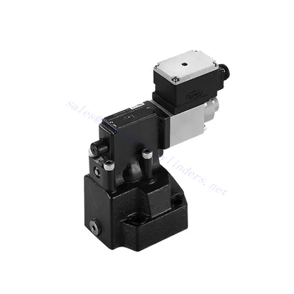
DRE(E) Series Proportional Pressure Reducing Hydraulic Valve
DRE(E) Series Proportional Pressure Reducing Hydraulic Valve
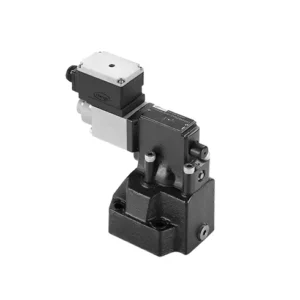
The DRE(E) series proportional pressure-reducing hydraulic valve is a cutting-edge hydraulic component that provides precise pressure control in hydraulic systems. With its advanced proportional control technology, this valve ensures optimal performance, efficiency, and safety.
The DRE(E) series proportional pressure-reducing hydraulic valve empowers hydraulic systems with precise pressure control, enhanced efficiency, and equipment protection. With its advanced proportional control technology, this valve ensures optimal performance across various applications. By following the recommended usage methods and maintenance guidelines, you can maximize the benefits and reliability of the DRE(E) series valve, elevating the pressure control and overall performance of your hydraulic system. Upgrade your hydraulic setup today and experience superior pressure regulation with the DRE(E) series proportional pressure-reducing hydraulic valve.
DRE(E) Series Proportional Pressure Reducing Hydraulic Valve Key Characteristics:
- Proportional Pressure Reduction:
- The DRE(E) series valve offers precise and proportional pressure reduction, enabling dynamic hydraulic pressure control.
- It ensures accurate pressure regulation, maintaining a consistent and safe pressure level within the hydraulic system.
- Повышение эффективности системы:
- This valve enables precise hydraulic pressure control, resulting in enhanced system efficiency and reduced energy consumption.
- By maintaining the desired pressure levels, it minimizes pressure fluctuations, optimizes system performance, and lowers operational costs.
- Safety and Equipment Protection:
- The DRE(E) series valve acts as a protective mechanism by limiting the pressure within the hydraulic system, safeguarding equipment and operators.
- It prevents excessive pressure build-up, reducing the risk of component damage, system failures, and potential accidents.
- Proportional Control Functionality:
- With its proportional control technology, the DRE(E) series valve offers smooth and precise pressure adjustment.
- It allows for real-time pressure control, enabling seamless integration into various hydraulic systems and applications.
DRE(E) Series Proportional Pressure Reducing Hydraulic Valve Parameter:
| General | ||||
| Жидкость | Минеральное масло, подходящее для уплотнений NBR и FKM | |||
| Фосфатный эфир для уплотнений FKM | ||||
| Диапазон температур жидкости | ℃ | -30 to +80 (NBR seals) | ||
| -20 до +80 (уплотнители FKM) | ||||
| Диапазон вязкости | мм2/с | 2.8 to 380 | ||
| Степень загрязнения | Максимально допустимая степень загрязнения жидкости: класс 9. NAS 1638 или 20/18/15, ISO4406 | |||
| Макс. рабочее давление | 315 bar | |||
| Port A、B、X | бар | 50; 100; 200; 315 | ||
| Макс. установочное давление | бар | In relation to Flow (Q), see characteristic curves | ||
| Min. settable pressure | =Min. settable pressure | |||
| Min. settable pressure at 0 command value | Separate and at zero pressure to tanks | |||
| Return oil pressure port Y | бар | Давление установки | Pressure range under Max. safety pressure | |
| Max. pressure safety (infinitely adjustable) | 50 bar | 10-60+20 бар | ||
| 100 bar | 10-120+20 бар | |||
| 200 bar | 10-220+20 бар | |||
| 315 bar | 10-340+20 бар | |||
| Max. pressure safety setting condition | When rated pressure is 50 bar, between 60 bar and 80 bar | |||
| When rated pressure is 100 bar, between120 bar and 140 bar | ||||
| When rated pressure is 200 bar, between 220 bar and 240 bar | ||||
| When rated pressure is 315 bar, between 340 bar and 360 bar | ||||
| Размер | 10 | 25 | 32 | |
| Макс. расход | 200 | 400 | 600 | |
| Pilot oil (for pilot valve)) | л/мин | 0.7 to 2 | ||
| Linearity | л/мин | ±3.5% | ||
| Повторяемость | <±2% | |||
| Гистерезис | with shimmy | without shimmy | ||
| ±1.5% P max (200Hz, amplitude 200mAsss) | ±4.5% P max | |||
| Switching time | 30~150ms(independent with the system) | |||
| Электрические данные | ||||
| Power | округ Колумбия | |||
| Min. solenoid current | mA | 100 | ||
| Max. solenoid current | mA | 800 | ||
| Сопротивление катушки | 19.5Ω at 20℃, Max. warm value: 28.8Ω | |||
| Working status | Continuous | |||
| Max. Ambient temperature range | +50℃ | |||
| Electrical connection | Plug-in connector to DIN 43 650/2 +SL/PG11 | |||
| Insulation to DIN 40 050 | IP 65 | |||
| Amplifier | VT2000 | |||
DRE(E) Series Proportional Pressure Reducing Hydraulic Valve Advantages:
• Используется для монтажа нижней подкладки
• Installation face follow DIN24340 E and ISO 6264
• Используется при установке блока масляного тракта
• Четыре диапазона давления
• Highest pressure protection structure (optional)
• Matching electronic amplifier VT-2000 type (must be ordered separately)
Usage Method Of DRE(E) Series Proportional Pressure Reducing Hydraulic Valve:
- Оценка системы:
- Оцените вашу гидравлическую систему и определите конкретные требования к контролю давления.
- Determine if the DRE(E) series valve is compatible with your system based on its pressure range, flow capacity, and other specifications.
- Выбор клапана:
- Choose the appropriate DRE(E) series valve variant based on your system parameters, pressure range, and flow requirements.
- Учитывайте максимальное номинальное давление, время отклика и условия эксплуатации.
- Установка:
- Тщательно следуйте инструкциям производителя по установке, обеспечивая правильное выравнивание и надежное крепление клапана.
- Подсоедините клапан к гидравлической системе, обеспечив герметичность соединений и правильное направление потока.
- Регулировка давления:
- Utilize the proportional control signal or adjustment mechanism provided with the DRE(E) series valve to set the desired pressure reduction level.
- Регулируйте клапан постепенно, контролируя показания манометра и реакцию системы, чтобы добиться точного регулирования давления.
How To Adjust Hydraulic Pressure Relief Valve?
Adjusting a hydraulic pressure relief valve allows you to regulate the maximum pressure within a hydraulic system. This is important for maintaining system integrity and preventing damage to components. Here’s a step-by-step guide on how to adjust a hydraulic pressure relief valve:
- Identify the Pressure Relief Valve:
- Locate the hydraulic pressure relief valve in your system. It is typically positioned in the hydraulic line or integrated into a manifold block.
- Understand the Valve Design:
- Familiarize yourself with the specific design of the pressure relief valve you are working with. Different valves may have varying adjustment mechanisms, such as a knob, screw, or locknut.
- Determine the Desired Pressure Setting:
- Assess the requirements of your hydraulic system and determine the desired maximum pressure. Consider the system’s specifications, load conditions, and safety limits.
- Подготовьте систему:
- Before making any adjustments, shut off the hydraulic system and relieve the pressure by moving the control levers back and forth or following the manufacturer’s recommended procedure.
- Locate the Adjustment Mechanism:
- Identify the adjustment mechanism on the pressure relief valve. It could be a knob, screw, or locknut positioned on the valve body or adjacent to it.
- Adjust the Valve:
- If the valve has a knob or handle, turn it clockwise to increase the pressure relief setting or counterclockwise to decrease it. If the valve has a screw, turn it clockwise to increase the ground or counterclockwise to drop it.
- Make Incremental Adjustments:
- When adjusting the pressure relief valve, make small, incremental changes to avoid sudden or drastic variations in pressure. This allows you to fine-tune the system and prevent potential damage.
- Observe the System:
- With each adjustment, observe the hydraulic system’s pressure gauge or indicator to see the effect of the changes. Ensure that the pressure stays within the desired range.
- Тестирование и проверка:
- Gradually increase the system’s pressure and monitor the pressure relief valve’s response. Ensure it relieves stress when the maximum set pressure is reached and maintains the desired maximum pressure.
- Заблокировать настройку:
- Once you have achieved the desired pressure setting, secure the adjustment mechanism to prevent unintended changes. Some valves may have a locking nut or set screw that can be tightened to hold the adjustment in place.
- Document the Adjustment:
- Keep a record of the adjusted pressure relief setting for future reference and maintenance purposes. This documentation will help maintain consistency and aid troubleshooting efforts.
Возможности и мощности завода:
(1) Сборка
Мы располагаем первоклассной независимой сборочной платформой для проведения исследований и разработок. Цех по производству гидравлических цилиндров имеет четыре полуавтоматические линии сборки подъемных цилиндров и одну автоматическую линию сборки цилиндров наклона с проектной годовой производственной мощностью 1 млн. штук. Цех по производству специальных цилиндров оснащен полуавтоматической очистной сборочной системой различных спецификаций с проектной годовой производственной мощностью 200 тыс. штук и оснащен известным обрабатывающим оборудованием с ЧПУ, обрабатывающим центром, высокоточным специальным оборудованием для обработки цилиндров, роботом-сварщиком, автоматической очистной машиной, автоматической сборочной машиной цилиндров и автоматической покрасочной производственной линией. Существующее критически важное оборудование насчитывает более 300 комплектов (комплектов). Оптимальное распределение и эффективное использование ресурсов оборудования позволяет обеспечить требования к точности изделий и удовлетворить потребности в высоком качестве продукции.


(2) Механическая обработка
Цех оснащен специализированным токарным центром с наклонной направляющей, обрабатывающим центром, высокоскоростным хонинговальным станком, сварочным роботом и другим сопутствующим оборудованием, которое позволяет обрабатывать цилиндрические трубы с максимальным внутренним диаметром 400 мм и максимальной длиной 6 м.

(3) Сварка

(4) Покраска и покрытие
С помощью небольших и средних цилиндрических автоматических линий нанесения лакокрасочных материалов на водной основе, обеспечивающих автоматическую загрузку и выгрузку роботом и автоматическое распыление, проектная производительность составляет 4000 изделий в смену;
У нас также имеется полуавтоматическая линия по производству краски для больших баллонов, приводимая в действие электроцепью, с проектной мощностью 60 ящиков в смену.


(5) Тестирование
У нас имеются первоклассные инспекционные центры и испытательные стенды, позволяющие гарантировать соответствие эксплуатационных характеристик цилиндра установленным требованиям.

Мы являемся одним из лучших производителей гидроцилиндров. Мы предлагаем широкий ассортимент гидроцилиндров. Мы также предлагаем сопутствующие товары. сельскохозяйственные редукторыМы экспортируем нашу продукцию клиентам по всему миру и заслужили хорошую репутацию благодаря превосходному качеству продукции и послепродажному обслуживанию. Мы приглашаем клиентов из Китая и других стран связаться с нами для деловых переговоров, обмена информацией и сотрудничать с нами!