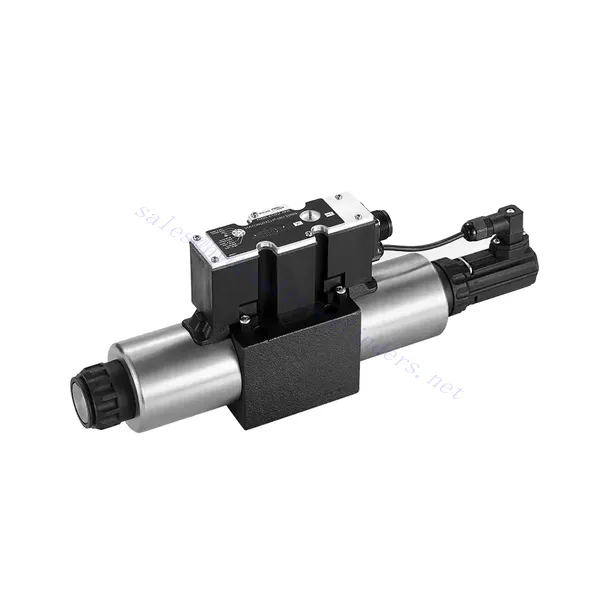
4WRE(E) Series Proportional Directional Hydraulic Valve
4WRE(E) Series Proportional Directional Hydraulic Valve
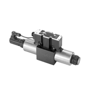
The 4WRE(E) series proportional directional hydraulic valve is a cutting-edge hydraulic component designed to deliver precise control and exceptional performance in hydraulic systems. This valve utilizes advanced proportional control technology to ensure accurate flow regulation and seamless directional changes.
The 4WRE(E) series proportional directional hydraulic valve empowers hydraulic systems with precise flow control, versatile directional changes, and energy efficiency. Its proportional control technology enables accurate and responsive flow adjustment, while the high flow capacity ensures reliable performance even in demanding applications. By following the recommended usage methods and maintenance guidelines, you can maximize the benefits and longevity of the 4WRE(E) series valve, elevating your hydraulic system to new levels of precision and performance. Upgrade your hydraulic setup today and experience the power of the 4WRE(E) series proportional directional hydraulic valve.
4WRE(E) Series Proportional Directional Hydraulic Valve Key Characteristics:
- Proportional Control Technology:
- The 4WRE(E) series valve features advanced proportional control technology, allowing for precise and proportional flow adjustment according to control signals.
- This feature enables accurate and responsive control, resulting in improved system performance and efficiency.
- Versatile Directional Control:
- With its proportional directional control capability, this valve offers versatile control over hydraulic fluid direction.
- It allows for seamless activation and deactivation of hydraulic components such as cylinders, motors, and actuators in different directions, enhancing system flexibility and productivity.
- Vysoká prietoková kapacita:
- The 4WRE(E) series valve is designed to handle high flow rates, making it suitable for applications requiring substantial hydraulic power.
- Jeho robustná konštrukcia zaisťuje spoľahlivý výkon aj v náročných podmienkach a poskytuje konzistentnú a efektívnu reguláciu prietoku.
- Energetická účinnosť:
- By employing advanced flow control mechanisms, this valve minimizes pressure drops and optimizes energy usage.
- Pomáha znižovať spotrebu energie, čo vedie k úsporám nákladov a environmentálnym výhodám.
4WRE(E) Series Proportional Directional Hydraulic Valve Parameter:
| Hydraulické | ||||
| Montážna poloha | voliteľné, najlepšie horizontálne | |||
| Veľkosť | 6 | 10 | ||
| Hmotnosť | 4WRE…L2X | kg | 2.2 | 6.3 |
| 4WREE…L2X | 2.4 | 6.5 | ||
| Nominal flow qnom at Δp = 10 bar | l/min | 8 16 32 | 25 50 75 | |
| Hysterézia | % | ≤0.1 | ||
| Reversal span | % | ≤0.05 | ||
| Opakovateľnosť | % | ≤0.05 | ||
| Maximálny prevádzkový tlak | Prístav ABP | bar | 315 | |
| Prístav T | bar | 210 | ||
| Tekutina | Minerálny olej vhodný pre tesnenia NBR a FKM | |||
| Fosfátový ester pre tesnenie FKM | ||||
| Ambient air temperature range | 4WRA…L2X | ℃ | -20℃ to 70℃ (-4°F to 158°F) | |
| 4WRAE…L2X | ℃ | -20℃ to 50℃ (-4°F to 122°F) | ||
| Rozsah viskozity | mm²/s | 20 až 380 (najlepšie 30 až 46) | ||
| Stupeň kontaminácie | NAS1638 trieda 9 alebo ISO 4406 trieda 20/18/15 | |||
| Elektrické údaje | ||||
| 1) solenoid | ||||
| Veľkosť | 6 | 10 | ||
| Typ napätia | DC | |||
| Signál požadovanej hodnoty | ±10 V alebo 4~20 mA | |||
| Max.current per solenoid | A | 2.5 | ||
| Odpor cievky | Hodnota za studena | Ω | 2.7 | 3.7 |
| Maximálna teplá hodnota | 4.05 | 5.55 | ||
| Povinnosť | % | ED 100% | ||
| Teplota cievky | ℃ | 150 | ||
| Ochrana ventilu podľa EN 60529 | Krytie IP 65 | |||
| 2) Control electronics | ||||
| Zosilňovač | 4WRE…L2X | VT-VSPA2-L2X | ||
| 4WREE…L2X | integrated(OBE) | |||
| Prevádzkové napätie | Menovité napätie | VDC | 24 | |
| Dolná hraničná hodnota | V. | 19.4 | ||
| Horná hraničná hodnota | V. | 35 | ||
| Spotreba prúdu zosilňovača | IMAX | A | < 2 | |
| IMAX | A | 3 | ||
4WRE(E) Series Proportional Directional Hydraulic Valve Advantages:
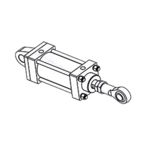
• Direct-acting proportional directional valve, used to control the flow and direction of liquid flow
• Panelová inštalácia
• The proportional solenoid actuates the valve core through the threaded connection, and the coil can be removed separately
• Spool position feedback
• Optional with built-in amplifier, 4WRAE…L2X type input can be A1 or F1
• Podpora napájania externého zosilňovača
Usage Method Of 4WRE(E) Series Proportional Directional Hydraulic Valve:
- Vyhodnotenie systému:
- Vyhodnoťte svoj hydraulický systém a identifikujte špecifické požiadavky na riadenie prietoku a smeru.
- Determine if the 4WRE(E) series valve is suitable based on its flow capacity, pressure rating, and compatibility with your system.
- Výber ventilu:
- Select the appropriate variant of the 4WRE(E) series valve based on your system parameters, flow requirements, and directional control needs.
- Zvážte faktory ako maximálny prietok, menovitý tlak, čas odozvy a prevádzkové podmienky.
- Inštalácia:
- Starostlivo dodržiavajte pokyny výrobcu na inštaláciu a zabezpečte správne zarovnanie a bezpečnú montáž ventilu.
- Make leak-free connections and ensure correct flow direction alignment to guarantee optimal performance.
- Control Signal Connection:
- Pripojte vodiče riadiaceho signálu ventilu k vhodnému ovládaciemu zariadeniu, ako je napríklad proporcionálny zosilňovač alebo elektronická riadiaca jednotka.
- Pre presné a citlivé ovládanie zabezpečte správne zapojenie a kompatibilitu medzi ventilom a ovládacím zariadením.
How To Adjust Valves With Hydraulic Lifters?
Adjusting valve lash on hydraulic lifters is a crucial maintenance task to ensure proper engine performance and prevent issues such as noisy valves or reduced power. Here’s a step-by-step guide on how to adjust valve lash on hydraulic lifters:
- Príprava:
- Ensure the engine is off and cool before starting the adjustment process.
- Familiarize yourself with the engine’s firing order and the specific valve lash specifications provided by the manufacturer for your engine model.
- Identify the Correct Cylinder:
- Locate the firing position of the engine by referring to the engine’s firing order diagram.
- Identify the cylinder that corresponds to the specific valve you want to adjust.
- Umiestnenie valca:
- Rotate the engine crankshaft manually using a socket wrench or the engine’s built-in turning mechanism.
- Position the cylinder you want to adjust at the top dead center (TDC) on the compression stroke. You can do this by aligning the timing marks on the crankshaft pulley or using a piston stop tool.
- Loosen the Rocker Arm:
- Locate the rocker arm on the specific valve you want to adjust.
- Loosen the rocker arm nut or adjuster screw using an appropriate wrench or socket.
- Adjust the Valve Lash:
- With the rocker arm loose, you can now adjust the valve lash. The valve lash is the clearance between the rocker arm and the valve stem.
- Use a feeler gauge to measure the existing valve lash. Insert the appropriate thickness gauge between the rocker arm and the valve stem.
- If the clearance is too tight, meaning the feeler gauge does not fit or has excessive resistance, you need to increase the valve lash. If the clearance is too loose, meaning the feeler gauge slides in too easily, you need to decrease the valve lash.
- To adjust the valve lash, tighten or loosen the rocker arm nut or adjuster screw accordingly. Refer to the manufacturer’s specifications for the recommended amount of adjustment to be made.
- Recheck the Valve Lash:
- After making the adjustment, recheck the valve lash using the feeler gauge to ensure it falls within the recommended specifications.
- Repeat the adjustment process if necessary until the correct valve lash is achieved.
- Repeat for Other Cylinders:
- Proceed to the next cylinder in the firing order and repeat steps 4 to 6 for each cylinder you want to adjust.
- Remember to rotate the crankshaft and position each cylinder at TDC on the compression stroke before adjusting its valve lash.
- Secure the Rocker Arm:
- Once the valve lash is properly adjusted for each cylinder, tighten the rocker arm nut or adjuster screw to the manufacturer’s recommended torque specification.
- Double-check that the valve lash remains within the specified range after tightening.
- Záverečné kontroly:
- Rotate the engine crankshaft a few times to ensure smooth rotation and check for any unusual noises or resistance.
- Start the engine and listen for any abnormal valve noises. If you hear excessive tapping or knocking, recheck the valve lash adjustment.
Schopnosť a kapacita továrne:
(1) Montáž
Disponujeme prvotriednou nezávislou výskumnou a vývojovou montážnou platformou. Dielňa na výrobu hydraulických valcov má štyri poloautomatické montážne linky zdvíhacích valcov a jednu automatickú montážnu linku naklápacích valcov s projektovanou ročnou výrobnou kapacitou 1 milión kusov. Dielňa na výrobu špeciálnych valcov je vybavená rôznymi špecifikáciami poloautomatického systému čistenia a montáže s projektovanou ročnou výrobnou kapacitou 200 000 kusov a je vybavená známym CNC obrábacím zariadením, obrábacím centrom, špeciálnym zariadením na vysoko presné spracovanie valcov, robotickým zváracím strojom, automatickým čistiacim strojom, automatickým montážnym strojom valcov a automatickou lakovacou výrobnou linkou. Existujúce kritické zariadenia majú viac ako 300 súprav (sád). Optimálne alokovanie a efektívne využívanie zdrojov zariadení zabezpečuje požiadavky na presnosť výrobkov a spĺňa požiadavky na vysokú kvalitu výrobkov.


(2) Obrábanie
Obrábacia dielňa je vybavená prispôsobeným sústružníckym centrom na šikmé koľajnice, obrábacím centrom, vysokorýchlostným honovacím strojom, zváracím robotom a ďalším súvisiacim zariadením, ktoré dokáže spracovať valcové rúry s maximálnym vnútorným priemerom 400 mm a maximálnou dĺžkou 6 metrov.

(3) Zváranie

(4) Maľovanie a natieranie
S malými a stredne veľkými valcovými automatickými linkami na nanášanie farieb na vodnej báze, na dosiahnutie automatického nakladania a vykladania robotmi a automatického striekania, je projektovaná kapacita 4000 kusov za smenu;
Máme tiež poloautomatickú linku na výrobu farieb pre veľké valce poháňané reťazou s projektovanou kapacitou 60 kusov za smenu.


(5) Testovanie
Disponujeme prvotriednymi kontrolnými zariadeniami a skúšobnými zariadeniami, ktoré zabezpečujú, že výkonnosť valca spĺňa požiadavky.

Sme jedným z najlepších výrobcov hydraulických valcov. Ponúkame komplexné hydraulické valce. Poskytujeme aj zodpovedajúce poľnohospodárske prevodovkyNaše produkty sme vyvážali klientom po celom svete a vďaka vynikajúcej kvalite produktov a popredajnému servisu sme si získali dobrú reputáciu. Vítame zákazníkov doma aj v zahraničí, ktorí nás kontaktujú za účelom rokovania o obchodných záležitostiach, výmeny informácií a spolupracovať s nami!