Pilotno upravljani smerni hidravlični ventili serije WEH
Pilotno upravljani smerni hidravlični ventili serije WEH
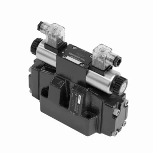
The WEH series directional hydraulic valves of pilot operated are advanced components that provide precise and efficient control over hydraulic systems. Designed to meet the demands of various industries, these valves offer exceptional performance, reliability, and versatility.
The WEH series directional hydraulic valves of pilot operated are reliable, high-performance components that empower operators with precise control and efficient fluid management in hydraulic systems. With their pilot-operated design, exceptional directional control, a wide range of configurations, and high flow capacity, these valves offer the reliability and versatility required in various industries. Following the recommended usage methods and adhering to regular maintenance practices, the WEH series valves will continue delivering exceptional performance. Upgrade your hydraulic system with the WEH series directional hydraulic valves operated and experience the benefits of precision, control, and reliability.
WEH Series Directional Hydraulic Valves Of Pilot Operated Key Characteristics:
- Pilot Operated Design:
- The WEH series valves utilize a pilot-operated design, which enhances their responsiveness and control accuracy.
- This design enables the valves to handle high-pressure applications, ensuring optimal performance easily.
- Smerni nadzor:
- These hydraulic valves excel in providing precise directional control of hydraulic fluid.
- Operaterji lahko enostavno upravljajo pretok tekočine in ga usmerjajo do različnih aktuatorjev ali komponent znotraj hidravličnega sistema.
- Wide Range of Configurations:
- The WEH series valves are available in various configurations, including various sizes, flow rates, and pressure ratings.
- This versatility allows them to be tailored to specific application requirements and system specifications.
- Visoka pretočnost:
- These valves are designed to handle high flow rates, making them suitable for applications that demand substantial fluid flow.
- Njihovi optimizirani notranji prehodi in robustna konstrukcija zagotavljajo minimalen padec tlaka in učinkovito upravljanje tekočin.
WEH Series Directional Hydraulic Valves Of Pilot Operated Parameter:
NG10
| Specifikacije | WEH10 type | |||||||||
| Max. operating pressure:P、A、B | 350 | |||||||||
| Pristanišče T | With external pilot oil drain bar | 315 | ||||||||
| With internal pilot oil drain bar | DC 210 AC 160 | |||||||||
| Pristanišče Y | With external pilot oil drain bar | DC 210 AC 160 | ||||||||
| Min. control pressure | With external pilot oil supply ( not apply to C、Z、 F、G、H、P、T、V) bar |
3-position valve 10 | ||||||||
| Spring-return 2-position valve 10 | ||||||||||
| Hydraulic-return 2-position valve 7 | ||||||||||
| With internal pilot oil supply ( apply to C、Z、F、 G、H、P、T、V) bar |
6.5 | |||||||||
| Max. control pressure bar | 250 | |||||||||
| Tekočina | Mineral oil,Phosphate ester | |||||||||
| Fluid temperature range ℃ | -30 to +80 ( NBR seals | |||||||||
| -20 to +80 ( FKM seals ) | ||||||||||
| Viscosity range mm2/s | 2,8 do 500 | |||||||||
| Switching pilot oil volume cm3 | 3-position valve 2.04 | |||||||||
| 2-position valve 4.08 | ||||||||||
| Switching times (= Valve switching time from the neutral position to the switched position)(AC and DC ) | ||||||||||
| Control pressure bar | 70 | 140 | 210 | 250 | ||||||
| AC | DC | AC | DC | AC | DC | AC | DC | |||
| 3-position valve ms | 30 | 65 | 25 | 60 | 20 | 55 | 15 | 50 | ||
| 2-position valve ms | 35 | 80 | 30 | 75 | 25 | 70 | 20 | 65 | ||
| Switching times (= Valve switching time from the switched position to the neutral position) | ||||||||||
| 3-position valve ms | 30 | |||||||||
| 2-position valve ms | 35 | 40 | 30 | 35 | 25 | 30 | 20 | 25 | ||
| Položaj namestitve | HC、HD、HK、HZ、HY Type hydraulic-return valves are installed horizontally, the rest can be installed arbitrarily | |||||||||
| Flow of shortest switching time L/min | about 35 | |||||||||
| Teža | Single solenoid valve kg | 6.7 | ||||||||
| Double solenoid valve kg | 7.1 | |||||||||
| Switching time regulator kg | 1.0 | |||||||||
| Reducing valve kg | 0.5 | |||||||||
NG16
| Specifikacije | WEH16… type | |||||||||||||
| Max. operating pressure:P、A、B | 350 | |||||||||||||
| Pristanišče T | With external pilot oil drain bar | 250 | ||||||||||||
| With internal pilot oil drain bar | DC 210 AC 160 | |||||||||||||
| Pristanišče Y | With external pilot oil drain bar | DC 210 AC 160 | ||||||||||||
| Min. control pressure | With external pilot oil supply ( not apply to C、Z、 F、G、H、P、T、V)bar |
3-position valve 14 | ||||||||||||
| Spring-return 2-position valve 14 | ||||||||||||||
| Hydraulic-return 2-position valve 14 | ||||||||||||||
| With internal pilot oil supply ( apply to C、Z、F、 G、 H、P、T、V) bar |
When applying prepressing or the flow is large correspondingly ,enginery of spool valve is 4.5 as C,Z,F,G,H,P,T and V | |||||||||||||
| Max. control pressure bar | 250 | |||||||||||||
| Tekočina | Mineral oil,Phosphate ester | |||||||||||||
| Fluid temperature range ℃ | -30 to +80 ( NBR seals | |||||||||||||
| -20 to +80 ( FKM seals ) | ||||||||||||||
| Viscosity range mm2/s | 2,8 do 500 | |||||||||||||
| Switching pilot oil volume | ||||||||||||||
| – Spring-centering 3-position valve cm3 | 5.72 | |||||||||||||
| – 2-position valve cm3 | 11.45 | |||||||||||||
| * * Switching times (= Valve switching time from the neutral position to the switched position)(AC and DC) | ||||||||||||||
| Control pressure bar | 50 | 150 | 250 | |||||||||||
| AC | DC | AC | DC | AC | DC | AC | DC | AC | DC | AC | DC | |||
| – Spring-centering 3-position valve ms | 35 | 65 | 30 | 60 | 30 | 58 | ||||||||
| – 2-position valve ms | 45 | 65 | 35 | 55 | 30 | 50 | ||||||||
| **Switching times (= Valve switching time from the neutral position to the switched position) | ||||||||||||||
| – Spring-centering 3-position valve ms | 30 | |||||||||||||
| – 2-position valve ms | 45 | 45 | 35 | 35 | 30 | 30 | ||||||||
| Položaj namestitve | C,D,K,Z,Y Type hydraulic-return valves are installed horizontally, the rest can be installed arbitrarily | |||||||||||||
| Flow of shortest switching time L/min | about 35 | |||||||||||||
| Weight kg | about 9.5 | |||||||||||||
NG25
| Specifikacije | WEH25… type | |||||||||||||||||
| Max. operating pressure:P、A、B | 350 | |||||||||||||||||
| Pristanišče T | With external pilot oil drain bar | 250 | ||||||||||||||||
| With internal pilot oil drain bar | DC 210 AC 160 | |||||||||||||||||
| Pristanišče Y | With external pilot oil drain bar | DC 210 AC 160 | ||||||||||||||||
| Min. control pressure | With external pilot oil supply ( not apply to C、Z、F、 G、H、P、T、V) bar |
Spring-centering 3-position valve 13 | ||||||||||||||||
| Spring-return 2-position valve 13 | ||||||||||||||||||
| Hydraulic-return 2-position valve 8 | ||||||||||||||||||
| With internal pilot oil supply ( apply to C、Z、F、 G、H、P、T、V) bar |
When applying prepressing or the flow is large correspondingly ,enginery of spool valve is 4.5 as C,Z,F,G,H,P,T and V | |||||||||||||||||
| Max. control pressure bar | 250 | |||||||||||||||||
| Tekočina | Mineral oil,Phosphate ester | |||||||||||||||||
| Fluid temperature range ℃ | -30 to +80 ( NBR seals | |||||||||||||||||
| -20 to +80 ( FKM seals ) | ||||||||||||||||||
| Switching pilot oil volume | ||||||||||||||||||
| – Spring-centering 3-position valve cm3 | 14.2 | |||||||||||||||||
| – 2-position valve cm3 | 28.4 | |||||||||||||||||
| * Switching times (= Valve switching time from the neutral position to the switched position)(AC and DC) | ||||||||||||||||||
| Control pressure bar | 50 | 140 | 210 | 250 | ||||||||||||||
| AC | DC | AC | DC | AC | DC | AC | DC | |||||||||||
| – Spring-centering 3-position valve ms | 50 | 85 | 40 | 75 | 35 | 70 | 30 | 65 | ||||||||||
| – 2-position valve ms | 120 | 160 | 100 | 130 | 85 | 120 | 70 | 105 | ||||||||||
| *Switching times (= Valve switching time from the neutral position to the switched position) | ||||||||||||||||||
| – Spring-centering 3-position valve ms | 40 | |||||||||||||||||
| – 2-position valve ms | 120 | 125 | 95 | 100 | 85 | 90 | 75 | 80 | ||||||||||
| Položaj namestitve | C,D,K,Z,Y Type hydraulic-return valves are installed horizontally, the rest can be installed arbitrarily | |||||||||||||||||
| Flow of shortest switching time L/min | about 35 | |||||||||||||||||
| Weight kg | about 18 | |||||||||||||||||
NG32
| Specifikacije | WEH32… type | |||||||||||||
| Max. operating pressure:P、A、B | 350 | |||||||||||||
| Pristanišče T | With external pilot oil drain bar | 250 | ||||||||||||
| With internal pilot oil drain bar | DC 210 AC 160 | |||||||||||||
| Pristanišče Y | With external pilot oil drain bar | DC 210 AC 160 | ||||||||||||
| Min. control pressure | With external pilot oil supply
With internal pilot oil supply |
3-position valve 8.5 | ||||||||||||
| Spring-return 2-position valve 10 | ||||||||||||||
| Hydraulic-return 2-position valve 15 | ||||||||||||||
| With internal pilot oil supply ( apply to C、Z、F、 G、H、P、T、V) bar |
When applying prepressing or the flow is large correspondingly ,enginery of spool valve is 4.5 as C,Z,F,G,H,P,T and V | |||||||||||||
| Max. control pressure bar | 250 | |||||||||||||
| Tekočina | Mineral oil,Phosphate ester | |||||||||||||
| Fluid temperature range ℃ | -30 to +80 ( NBR seals | |||||||||||||
| -20 to +80 ( FKM seals ) | ||||||||||||||
| Viscosity range mm2/s | 2,8 do 500 | |||||||||||||
| Switching pilot oil volume | ||||||||||||||
| – Spring-centering 3-position valve cm3 | 29.4 | |||||||||||||
| – 2-position valve cm3 | 58.8 | |||||||||||||
| * Switching times (= Valve switching time from the neutral position to the switched position)(AC and DC) | ||||||||||||||
| Control pressure bar | 50 | 150 | 250 | |||||||||||
| AC | DC | AC | DC | AC | DC | |||||||||
| – Spring-centering 3-position valve ms | 65 | 80 | 50 | 90 | 35 | 105 | ||||||||
| – 2-position valve ms | 100 | 130 | 75 | 100 | 60 | 115 | ||||||||
| *Switching times (= Valve switching time from the neutral position to the switched position) | ||||||||||||||
| – Spring-centering 3-position valve ms | ( DC :50,AC :60) | |||||||||||||
| – 2-position valve ms | 115 | 90 | 35 | 70 | 65 | 65 | ||||||||
| Položaj namestitve | C、D、K、Z、YType hydraulic-return valves are installed horizontally, the rest can be installed arbitrarily | |||||||||||||
| Flow of shortest switching time L/min | about 50 | |||||||||||||
| Weight kg | about 36 | |||||||||||||
WEH Series Directional Hydraulic Valves Of Pilot Operated Advantages:
• Electrohydraulic directioanl valve directioanls the oil path by controlling the main spool
• WEH electrohydraulic control
• Installation face follow DIN 24340 A, ISO 4401 and CETOP-RP 121H Sub-plate mounting connection
• Wet DC or AC solenoid (optional)
• With manual emergency control
• Electropneumatic connection as single or center connection
• Spring or hydraulic alignment or bias
Usage Method Of WEH Series Directional Hydraulic Valves Of Pilot Operated:
- Sistemska integracija:
- Identify the optimal location for installing the WEH series valves within the hydraulic system, considering the desired flow path and control requirements.
- Zagotovite združljivost s specifikacijami tlaka in pretoka sistema.
- Ventile varno namestite z ustreznimi nosilci ali montažno opremo.
- Pilot Control Setup:
- Connect the pilot control lines to the designated ports on the valves, following the manufacturer’s instructions.
- Ensure proper sizing and routing of the pilot lines to maintain optimal control signal integrity.
- Priključki za tekočine:
- Za varne in netesne povezave izberite združljive hidravlične priključke in cevi.
- Med namestitvijo upoštevajte navodila proizvajalca za pravilne vrednosti navora.
- Za zagotovitev zanesljivega tesnjenja uporabite ustrezna tesnilna sredstva za navoje ali trak.
- Nadzor in prilagajanje:
- To operate the WEH series valves, utilize the recommended control method, such as manual levers or electrical controls.
- Adjust the valves’ settings to achieve the desired flow direction and rates, ensuring optimal performance.
How Do Hydraulic Valve Lifters Work?
Hydraulic valve lifters, also known as hydraulic tappets or hydraulic lash adjusters, play a vital role in the proper operation of an internal combustion engine. They are responsible for maintaining the proper clearance, or “lash,” between the engine’s camshaft and valve train components. Here’s an overview of how hydraulic valve lifters work:
- Struktura:
- Hydraulic valve lifters are small cylindrical devices typically made of metal.
- They are between the camshaft and the engine’s valve train components, such as the pushrods, rocker arms, or overhead cam followers.
- Hydraulic Operation:
- Inside the hydraulic valve lifter, a small piston mechanism operates based on hydraulic pressure.
- The lifter is filled with hydraulic fluid, typically engine oil, which acts as a working fluid.
- Camshaft Interaction:
- The camshaft has lobes or eccentric shapes that push against the lifters as it rotates.
- As the camshaft lobe comes into contact with the lifter, it applies a force that compresses its internal piston.
- Lash Adjustment:
- When the lifter’s piston is compressed, it pushes the hydraulic fluid out of the lifter through a small orifice.
- This hydraulic fluid is expelled into the engine’s oil galleries or passages.
- Lash Compensation:
- The expelled hydraulic fluid creates a hydraulic cushion or “spring” effect, compensating for any clearance or lash between the camshaft lobe and the valve train components.
- This compensation eliminates excessive clearance and ensures that the valve train remains in constant contact with the camshaft lobes.
- Maintenance of Lash:
- If there is excessive clearance or lash in the valve train due to wear or other factors, the lifter’s internal piston will extend further to maintain the necessary hydraulic pressure.
- This extended position allows the lifter to take up the additional clearance, thus maintaining proper valve lash.
- Oil Pressure and Lubrication:
- The hydraulic valve lifters rely on the engine’s oil pressure for proper operation.
- The oil pump circulates oil through the engine, and the lifters receive a continuous oil supply to maintain hydraulic pressure and lubrication.
Zmogljivost in zmogljivost tovarne:
(1) Sestavljanje
Imamo prvovrstno neodvisno platformo za raziskave in razvoj. Delavnica za proizvodnjo hidravličnih cilindrov ima štiri polavtomatske montažne linije za dvižne cilindre in eno avtomatsko montažno linijo za nagibne cilindre z letno proizvodno zmogljivostjo 1 milijona kosov. Delavnica za posebne cilindre je opremljena z različnimi specifikacijami polavtomatskega sistema za čiščenje in montažo z letno proizvodno zmogljivostjo 200.000 kosov ter znano CNC obdelovalno opremo, obdelovalnim centrom, visoko precizno posebno opremo za obdelavo cilindrov, robotskim varilnim strojem, avtomatskim čistilnim strojem, avtomatskim strojem za montažo cilindrov in avtomatsko proizvodno linijo za barvanje. Obstoječa kritična oprema obsega več kot 300 kompletov (kompletov). Optimalna razporeditev in učinkovita uporaba opremnih virov zagotavljata zahteve glede natančnosti izdelkov in izpolnjujeta visoke zahteve glede kakovosti izdelkov.


(2) Strojna obdelava
Strojna delavnica je opremljena s prilagojenim centrom za struženje nagnjenih tirnic, obdelovalnim centrom, visokohitrostnim strojem za honanje, varilnim robotom in drugo sorodno opremo, ki lahko obdeluje cilindrične cevi z največjim notranjim premerom 400 mm in največjo dolžino 6 metrov.

(3) Varjenje

(4) Barvanje in premazovanje
Z majhnimi in srednje velikimi cilindričnimi avtomatskimi linijami za barvanje na vodni osnovi, za doseganje avtomatskega nakladanja in razkladanja robotov ter avtomatskega brizganja, je projektna zmogljivost 4000 kosov na izmeno;
Imamo tudi polavtomatsko linijo za proizvodnjo barv za velike jeklenke, ki jo poganja veriga, s projektno zmogljivostjo 60 zabojev na izmeno.


(5) Testiranje
Imamo prvovrstne inšpekcijske prostore in testne postaje, s katerimi zagotavljamo, da delovanje jeklenke izpolnjuje zahteve.

Smo eden najboljših proizvajalcev hidravličnih cilindrov. Ponujamo vam celovite hidravlične cilindre. Zagotavljamo tudi ustrezne kmetijski menjalnikiNaše izdelke smo izvozili strankam po vsem svetu in si prislužili dober ugled zaradi vrhunske kakovosti izdelkov in poprodajnih storitev. Z veseljem vas vabimo, da nas kontaktirate za poslovne dogovore, izmenjavo informacij in ... sodelujte z nami!