3DRE/M(E)-serien 3-vägs pilotstyrd proportionell tryckreducerande hydraulventil
3DRE/M(E)-serien 3-vägs pilotstyrd proportionell tryckreducerande hydraulventil
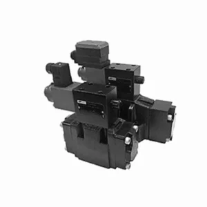
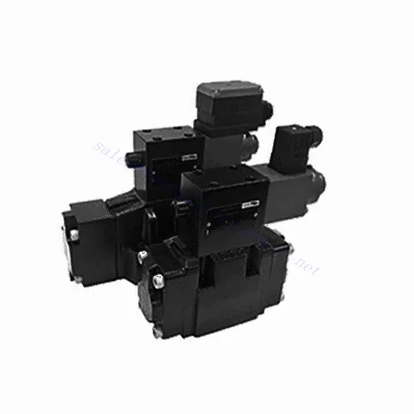
The 3DRE/M(E) series 3-way pilot-operated proportional pressure-reducing hydraulic valve is a cutting-edge hydraulic component designed to deliver accurate pressure control in hydraulic systems. With its advanced pilot-operated proportional control technology, this valve ensures precise regulation, efficient performance, and reliable operation.
The 3DRE/M(E) series 3-way proportional pressure-reducing hydraulic valve empowers hydraulic systems with precise pressure control, efficiency, and reliable performance. With its advanced proportional control technology and 3-way configuration, this valve offers versatility and flexibility in pressure regulation across different hydraulic circuits. By following the recommended usage methods and maintenance guidelines, you can maximize the benefits and longevity of the 3DRE/M(E) series valve, optimizing pressure control and overall performance in your hydraulic system. Upgrade your hydraulic setup today and experience superior pressure regulation with the 3DRE/M(E) series 3-way proportional pressure-reducing hydraulic valve.
3DRE/M(E) Series 3-way Pilot Operated Proportional Pressure Reducing Hydraulic Valve Key Characteristics:
- Proportionell tryckreglering:
- The 3DRE/M(E) series valve offers precise and proportional pressure control, enabling dynamic adjustment of hydraulic pressure levels.
- This feature ensures accurate pressure regulation, maintaining a consistent and safe pressure within the hydraulic system.
- Pilotstyrd design:
- With its pilot-operated design, the valve delivers enhanced precision and responsiveness in pressure control.
- It utilizes a pilot valve to modulate the main valve, allowing for precise adjustments and improved control over pressure reduction.
- 3-vägskonfiguration:
- The 3DRE/M(E) series valve features a versatile 3-way configuration, providing flexibility in controlling pressure across different hydraulic circuits.
- It allows for simultaneous pressure reduction in one circuit while supplying pressure to another course.
- Effektiv prestanda:
- By utilizing advanced proportional control technology, the valve ensures efficient performance, optimizing energy usage and reducing operational costs.
- It minimizes pressure fluctuations, enhancing system efficiency and contributing to overall productivity.
3DRE/M(E) Series 3-way Pilot Operated Proportional Pressure Reducing Hydraulic Valve Parameter:
| Hydraulisk | ||||||||
| Installationsposition | valfritt, helst horisontellt | |||||||
| Storlek | 6 | 10 | ||||||
| Vikt | 4WRA…L2X | kg | 2 | 6.6 | ||||
| 4WRAE…L2X | 2.2 | 6.8 | ||||||
| Rated flow qnom,when Δp = 10 bar | l/min | 7、15、26 | 30、60 | |||||
| Hysteres | % | ≤5 | ||||||
| Repeterbarhet | % | ≤1 | ||||||
| Responskänslighet | % | ≤0,5 | ||||||
| Max. driftstryck | Port s A B P | bar | 315 | |||||
| Port T | bar | 210 | ||||||
| Vätska | Mineralolja lämplig för NBR- och FKM-tätningar | |||||||
| Fosfatester för FKM-tätning | ||||||||
| Vätsketemperaturområde | 4WRA…L2X | ℃ | -20℃ to 70℃(-4°F to 158°F) | |||||
| 4WRAE…L2X | ℃ | -20℃ to 50℃(-4° F to 122° F) | ||||||
| Viskositetsområde | mm²/s | 20 to 380(preferably 30 to 46) | ||||||
| Grad av kontaminering | NAS1638 class9 or ISO 4406 class 20/18/15 | |||||||
| Elektriska data | ||||||||
| 1)solenoid | ||||||||
| Spänningstyp | likström | |||||||
| Kommandovärdessignal | ±10V or 4~20mA | |||||||
| Max. ström per solenoid | En | 2.5 | 1.5 | 0.8 | ||||
| Spolmotstånd | Cold value | Ω | 2 | 4.8 | 19.5 | |||
| Max. värmevärde | 3 | 7.2 | 28.8 | |||||
| Tull | % | ED100% | ||||||
| Spoltemperatur | ℃ | 150 | ||||||
| Ventilskydd enligt EN 60529 | IP65 | |||||||
| 2)Control electronics | ||||||||
| Förstärkare | 4WRA…L2X | VT-VSPA2-L2X | ||||||
| 4WRAE…L2X | Integrated in the valve(OBE) | |||||||
| Driftspänning | Nominell spänning | VDC | 24 | |||||
| Nedre gränsvärde | V | 21/22(4WRA),19(4WRAE) | ||||||
| Övre gränsvärde | V | 35 | ||||||
| Förstärkarens strömförbrukning | Imax | En | <1.8 | |||||
| Imax | En | 3 | ||||||
Fördelar med 3DREP(E)-seriens 3-vägs proportionella tryckreducerande hydraulventil:
• The pilot-operated relief valve is used for the pressure reduction from P to A and the overflow function from A to T.
• Used for bottom sub-plate mounting, driven by proportional solenoid.
• The mounting surface is in accordance with DIN24 340, type A, ISO4401 and CETOP-RP 121H
• The maximum safety pressure is available for selection.
• Spool spring alignmentalignment
• 3DRE electronic controller: european card specification amplifier VT-VSPA1-1/VT-VSPD-1
• Set point the pressure characteristic curve is linear
• 3DRE(M)E series integrated electronic controller
• Setting value caused by manufacturing error-the deviation of the pressure characteristic curve is small
• The slope of the pressure increase and decrease can be adjusted independently
Användningsmetod för 3DREP(E)-seriens 3-vägs proportionella tryckreducerande hydraulventil:
- Systemutvärdering:
- Utvärdera ditt hydraulsystem och identifiera de specifika tryckregleringskraven för varje krets.
- Determine if the 3DRE/M(E) series valve is suitable based on its pressure range, flow capacity, and compatibility with your system.
- Ventilval:
- Select the appropriate variant of the 3DRE/M(E) series valve based on your system parameters, pressure range, and flow requirements.
- Tänk på maximalt tryck, reaktionstid och driftsförhållanden.
- Installation:
- Följ tillverkarens installationsanvisningar noggrant och säkerställ korrekt inriktning och säker montering av ventilen.
- Anslut ventilen till hydraulsystemet och säkerställ att anslutningarna är läckfria och att flödesriktningen är korrekt inställd.
- Tryckjustering:
- Utilize the pilot valve control mechanism provided with the 3DRE/M(E) series valve to adjust the desired pressure reduction level for each circuit.
- Gradually adjust the pilot valve control to achieve the desired pressure control, monitoring the pressure gauge readings and system response.
How To Adjust Hydraulic Valves?
Adjusting hydraulic valves is a crucial task to ensure proper flow control and system performance in hydraulic applications. Here’s a step-by-step guide on how to adjust hydraulic valves:
- Identifiera ventilen:
- Determine the type of hydraulic valve you need to adjust: pressure relief valve, flow control valve, directional control valve, or any other type.
- Locate the valve within your hydraulic system. It can be positioned near the pump, in the control valve manifold, or within specific hydraulic components.
- Samla de nödvändiga verktygen:
- Before starting the adjustment process, gather the required tools, such as an adjustable wrench, a screwdriver, a pressure gauge (if applicable), and any specialized tools recommended by the valve manufacturer.
- Understand the Valve Function:
- Familiarize yourself with the purpose and function of the valve you are adjusting. Refer to the valve’s technical documentation or consult the manufacturer’s guidelines for specific details.
- Determine the Desired Setting:
- Identify the desired setting or parameter you want to achieve by adjusting the valve. This could be pressure, flow rate, direction, or any other adjustable parameter based on the valve type.
- Preliminary Checks:
- Ensure that the hydraulic system is depressurized before attempting any adjustments. This can be done by shutting down the system and relieving residual pressure through appropriate valves.
- Access the Adjustment Mechanism:
- Locate the adjustment mechanism on the valve. It can be a set screw, locknut, knob, or other similar devices depending on the valve type.
- Some valves may require removing a protective cap or cover to access the adjustment mechanism.
- Gör stegvisa justeringar:
- Using the appropriate tool, make small incremental adjustments to the valve according to the desired setting.
- Follow the manufacturer’s guidelines to determine the direction (clockwise or counterclockwise) and the amount of adjustment required.
- Make gradual adjustments and periodically check the system’s response to ensure you are moving in the desired direction.
- Test and Monitor:
- After each adjustment, activate the hydraulic system and observe its performance.
- Use appropriate measurement tools (pressure gauge, flow meter, etc.) to verify that the valve is operating within the desired range.
- Monitor the system for any abnormalities or unexpected behavior. If necessary, make further adjustments to fine-tune the valve setting.
- Lock the Adjustment (if applicable):
- Once you achieve the desired setting, secure the adjustment mechanism to prevent unintended changes.
- This can be done by tightening a locknut, securing a set screw, or using any other method recommended by the valve manufacturer.
Fabrikens kapacitet och kapacitet:
(1) Montering
Vi har en förstklassig oberoende forsknings- och utvecklingsplattform. Verkstaden för tillverkning av hydraulcylindrar har fyra halvautomatiska monteringslinjer för lyftcylindrar och en automatisk monteringslinje för tiltcylindrar, med en planerad årlig produktionskapacitet på 1 miljon enheter. Specialcylinderverkstaden är utrustad med olika specifikationer för ett halvautomatiskt rengöringsmonteringssystem med en planerad årlig produktionskapacitet på 200 000 och utrustad med känd CNC-bearbetningsutrustning, ett fleroperationscenter, en specialutrustning för högprecisionscylindrar, en robotsvetsmaskin, en automatisk rengöringsmaskin, en automatisk cylindermonteringsmaskin och en automatisk produktionslinje för målning. Befintlig kritisk utrustning på mer än 300 set (set). Optimal allokering och effektiv användning av utrustningsresurser säkerställer produkternas noggrannhetskrav och uppfyller produkternas höga kvalitetsbehov.


(2) Maskinbearbetning
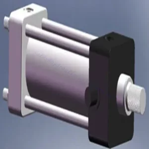
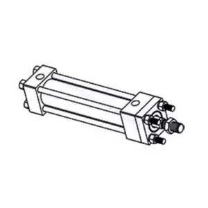
Bearbetningsverkstaden är utrustad med en specialanpassad svarvcentral för lutande räls, bearbetningscenter, höghastighetshönsmaskin, svetsrobot och annan relaterad utrustning, som kan hantera bearbetning av cylinderrör med en maximal innerdiameter på 400 mm och en maximal längd på 6 meter.

(3) Svetsning

(4) Målning och ytbehandling
Med små och medelstora cylindriska automatiska vattenbaserade färgbeläggningslinjer, för att uppnå automatisk robotlastning och lossning samt automatisk sprutning, är den designade kapaciteten 4000 stycken per skift;
Vi har även en halvautomatisk färgproduktionslinje för stora cylindrar som drivs av en släpkedja, med en designkapacitet på 60 lådor per skift.


(5) Testning
Vi har förstklassiga inspektionsanläggningar och testbäddar för att säkerställa att cylinderns prestanda uppfyller kraven.

Vi är en av de bästa tillverkarna av hydraulcylindrar. Vi kan erbjuda ett heltäckande utbud av hydraulcylindrar. Vi tillhandahåller även motsvarande jordbruksväxellådorVi har exporterat våra produkter till kunder över hela världen och fått ett gott rykte tack vare vår överlägsna produktkvalitet och kundservice. Vi välkomnar kunder både hemma och utomlands att kontakta oss för att förhandla affärer, utbyta information och samarbeta med oss!