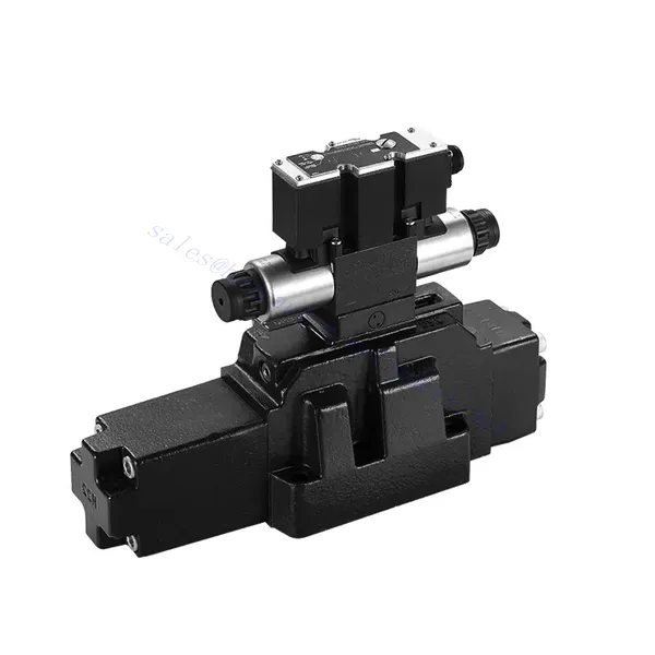
4WRZ/H(E) Series Pilot Operated Proportional Directional Hydraulic Valve
4WRZ/H(E) Series Pilot Operated Proportional Directional Hydraulic Valve
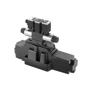
The 4WRZ/H(E) series pilot-operated proportional directional hydraulic valve is a state-of-the-art component designed to provide exceptional precision, control, and efficiency in hydraulic systems. With its advanced pilot-operated proportional control technology, this valve enables accurate flow regulation and seamless directional changes.
The 4WRZ/H(E) series pilot-operated proportional directional hydraulic valve empowers hydraulic systems with precise flow control, versatile directional changes, and energy efficiency. Its pilot-operated proportional control technology ensures accurate and responsive flow adjustment, while the high flow capacity guarantees reliable performance even in demanding applications. By following the recommended usage methods and maintenance guidelines, you can maximize the benefits and longevity of the 4WRZ/H(E) series valve, elevating your hydraulic system to new levels of precision and control. Upgrade your hydraulic setup today and experience the power of the 4WRZ/H(E) series pilot-operated proportional directional hydraulic valve.
4WRZ/H(E) Series Pilot Operated Proportional Directional Hydraulic Valve Key Characteristics:
- Pilot Tarafından Yönetilen Oransal Kontrol
- The 4WRZ/H(E) series valve utilizes pilot-operated proportional control technology, allowing precise and proportional flow adjustment based on control signals.
- Bu özellik, hassas ve duyarlı bir kontrol sağlayarak sistem performansının artmasını, enerji tüketiminin azalmasını ve üretkenliğin artmasını sağlar.
- Çok Yönlü Yön Kontrolü
- Bu valf, hidrolik sıvı yönü üzerinde çok yönlü kontrol sağlayarak çok çeşitli uygulamalar için uygundur.
- Silindirler, motorlar ve aktüatörler gibi hidrolik bileşenlerin farklı yönlerde sorunsuz bir şekilde etkinleştirilmesini ve devre dışı bırakılmasını sağlayarak sistem esnekliğini ve uyarlanabilirliğini artırır.
- Yüksek Akış Kapasitesi
- The 4WRZ/H(E) series valve is engineered to handle high flow rates, making it ideal for applications that require substantial hydraulic power.
- Sağlam yapısı, zorlu koşullarda bile güvenilir performans sağlayarak tutarlı ve verimli akış kontrolü sağlar.
- Enerji Verimliliği
- Pilot kumandalı oransal kontrolü entegre eden bu vana, basınç düşüşlerini en aza indirir ve enerji kullanımını optimize eder.
- Enerji tüketimini azaltmaya yardımcı olur, bu da maliyet tasarrufu ve çevresel faydalar sağlar.
4WRZ/H(E) Series Pilot Operated Proportional Directional Hydraulic Valve Parameter:
| GeneraL | |||||||
| Valve type | WRZ | WRZE | |||||
| Kurulum | Optional,preferably horizontal | ||||||
| Depolama sıcaklığı aralığı | ℃ | -20 ila +80 | |||||
| Ortam sıcaklığı aralığı | ℃ | -20 ila +70 | -20 ila +50 | ||||
| Ağırlık | NS 10 | kilogram | 7.8 | 8 | |||
| NS 16 | kilogram | 13.4 | 13.6 | ||||
| NS 25 | kilogram | 18.2 | 18.4 | ||||
| NS 32 | kilogram | 42.2 | 42.4 | ||||
| Hidrolik (measured with HLPAG.p=100bar : 40 ℃ ± 5 ℃) | |||||||
| Boyut | 10 | 16 | 25 | 32 | |||
| Çalışma basıncı | Pilot valve | External pilot oil supply | çubuk | 30 to 100 bar | |||
| Internal pilot oil supply | çubuk | 100 to 350 with “D3” only | |||||
| Ana vana | çubuk | to 315 | to 350 | to 350 | to 350 | ||
| Geri dönüş basıncı | Port T (Port R) (external pilot oil drain)) | çubuk | to 315 | to 250 | to 250 | 150'ye kadar | |
| Port T (internal pilot oil drain) | çubuk | to 30 | to 30 | to 30 | to 30 | ||
| Liman Y | çubuk | to 30 | to 30 | to 30 | to 30 | ||
| Pilot oil volume input signal 0- 100 % | cm3 | 1.7 | 4.6 | 10 | 26.5 | ||
| Pilot oil flow in port X and Y with a stepped input signal 0- 100 % | 3.5 | 5.5 | 7 | 15.9 | |||
| Flow of the main valve | L/dak | to 170 | to 460 | to 870 | to 1600 | ||
| Hidrolik sıvı | L/dak | Mineral oil (HL, HLP) to DIN 51524 Further fluids on enquiry | |||||
| Hidrolik sıvı sıcaklık aralığı | ℃ | -20 to +80(preferably +40 to +50) | |||||
| Viskozite aralığı | mm2/S | 20 to 380(preferably 30 to 46) | |||||
| Kirlilik derecesi | Maximum permissible degree of contamination of the pressure fluid is to NAS 1638 or ISO 4406(c) | A filter with a minimum retention rate of βx ≥ 75 is recommended | |||||
| Pilot valve | NAS 1638 class 7 | x=5 | |||||
| Ana vana | NAS 1638 class 9 | x=15 | |||||
| Histerezis | % | ≤6 | |||||
| Elektrik | |||||||
| Valve type | WRZ | WRZE | |||||
| Type of protection of the valve to EN 60529 | IP65 with cable socket mounted and locked | ||||||
| Voltaj türü | DC | ||||||
| Command value overlap | % | 15 | |||||
| Max. current | A | 1.5 | 2.5 | ||||
| Solenoid coil resisance | Cold value at 20℃ | Ω | 4.8 | 2 | |||
| Maksimum sıcak değer | Ω | 7.2 | 3 | ||||
| Döngüsel süre faktörü | % | 100 | |||||
| Bobin sıcaklığı | ℃ | 150'ye kadar | |||||
| EN 60529'a göre vana koruması | IP65 | ||||||
| Kontrol elektroniği | |||||||
| External amplifier for type WRZ | VT- VSPA2-L2X/… | ||||||
| Komut değeri sinyali | -Voltage input “A1” | V | ±10 | ||||
| –Current input “F1” | mA | 4 to 20 | |||||
4WRZ/H(E) Series Pilot Operated Proportional Directional Hydraulic Valve Advantages:
• Pilot-operated two-stage proportional directional valve, used to control the size and direction of the liquid flow
• Threaded connection type proportional solenoid, the coil can be disassembled separately
• Sub-plate mounting connection structure, connection size conforms to DIN2430 and ISO4401 standards
• Makara yayı hizalama hizalaması
• WRZE type with integrated proportional amplifierr
• WRZ type external amplifier (order separately)
Usage Method Of 4WRZ/H(E) Series Pilot Operated Proportional Directional Hydraulic Valve:
- Sistem Değerlendirmesi
- Hidrolik sisteminizi değerlendirin ve özel akış ve yön kontrol gereksinimlerini belirleyin.
- Determine if the 4WRZ/H(E) series valve is suitable based on its flow capacity, pressure rating, and compatibility with your system.
- Valf Seçimi
- Select the appropriate variant of the 4WRZ/H(E) series valve based on your system parameters, flow requirements, and directional control needs.
- Maksimum akış hızı, basınç derecesi, tepki süresi ve çalışma koşulları gibi faktörleri göz önünde bulundurun.
- Kurulum
- Üreticinin montaj talimatlarını dikkatlice izleyin, vananın doğru hizalanmasını ve güvenli bir şekilde monte edilmesini sağlayın.
- Sızıntı yapmayan bağlantılar oluşturun ve en iyi performansı garanti etmek için doğru akış yönü hizalamasını sağlayın.
- Kontrol Sinyali Bağlantısı
- Vananın kontrol sinyal kablolarını orantılı amplifikatör veya elektronik kontrol ünitesi gibi uygun bir kontrol cihazına bağlayın.
- Doğru ve duyarlı kontrol için vana ile kontrol cihazı arasında uygun kablolama ve uyumluluğun sağlanması gerekir.
How To Bleed Hydraulic Control Valve?
Bleeding a hydraulic control valve is an essential maintenance procedure to remove any trapped air or gas from the system, ensuring optimal performance and efficiency. Here’s a step-by-step guide on how to bleed a hydraulic control valve:
- Sistemi Hazırlayın:
- Ensure that the hydraulic system is turned off and that the pressure is relieved. This step is crucial for your safety and to prevent any accidental movement or release of high-pressure fluids.
- Locate the bleeder valve or bleed screw on the hydraulic control valve. It is typically located on the top or side of the valve body and may have a protective cap or cover.
- Positioning and Safety Measures:
- Place a suitable container or absorbent material beneath the bleed valve to catch any fluid that may be expelled during the bleeding process.
- Wear appropriate personal protective equipment (PPE), such as safety goggles and gloves, to protect yourself from hydraulic fluid splashes.
- Opening the Bleed Valve:
- Using an appropriate wrench or tool, carefully loosen the bleed valve or screw counterclockwise. Be cautious not to fully remove it at this stage.
- The bleed valve may have an O-ring or sealing washer. Take note of its position and ensure it is in good condition.
- System Activation:
- Activate the hydraulic system by turning on the power source, such as an engine or hydraulic pump.
- Operate the control mechanism associated with the hydraulic control valve, such as a joystick or lever, to allow fluid flow through the valve.
- Bleeding Process:
- Slowly open the bleed valve by turning it counterclockwise until you start to see hydraulic fluid or air bubbles escaping from the valve.
- Allow the fluid to flow for a few seconds or until you observe a steady stream of fluid without any air bubbles. This indicates that the air has been purged from the system.
- Be cautious not to open the bleed valve too much, as it may lead to excessive fluid loss or system damage.
- Closing the Bleed Valve:
- Once you have successfully bled the system, close the bleed valve by turning it clockwise. Ensure it is tightened securely but avoid over-tightening.
- Check for any leaks around the bleed valve or other connections. If you notice any leaks, address them promptly to prevent further issues.
- System Check:
- Turn off the hydraulic system and inspect the fluid level in the reservoir. Add hydraulic fluid as necessary to maintain the recommended level.
- Test the operation of the hydraulic control valve and associated components to ensure proper functionality.
Fabrikanın Kapasitesi ve Kapasitesi:
(1) Meclis
Birinci sınıf bağımsız bir araştırma ve geliştirme montaj platformumuz bulunmaktadır. Hidrolik silindir üretim atölyemizde, yıllık 1 milyon adet üretim kapasitesine sahip dört adet yarı otomatik kaldırma silindiri montaj hattı ve bir adet otomatik devirme silindiri montaj hattı bulunmaktadır. Özel silindir atölyemiz, yıllık 200.000 adet üretim kapasitesine sahip çeşitli özelliklerde yarı otomatik temizleme montaj sistemiyle donatılmıştır. Ayrıca, ünlü CNC işleme ekipmanları, bir işleme merkezi, yüksek hassasiyetli silindir işleme özel ekipmanları, bir robot kaynak makinesi, bir otomatik temizleme makinesi, otomatik silindir montaj makinesi ve otomatik boyama üretim hattı ile donatılmıştır. 300'den fazla setten oluşan kritik ekipmanlar mevcuttur. Ekipman kaynaklarının optimum dağılımı ve verimli kullanımı, ürünlerin hassasiyet gereksinimlerini karşılar ve ürünlerin yüksek kalite ihtiyaçlarını karşılar.


(2) İşleme
İşleme atölyesi, maksimum 400 mm iç çapa ve maksimum 6 metre uzunluğa sahip silindir borularının işlenmesini gerçekleştirebilen özel eğimli ray torna merkezi, işleme merkezi, yüksek hızlı honlama makinesi, kaynak robotu ve diğer ilgili ekipmanlarla donatılmıştır.

(3) Kaynak

(4) Boyama ve kaplama
Küçük ve orta ölçekli silindirli otomatik su bazlı boya kaplama hatlarında, otomatik robot yükleme-boşaltma ve otomatik püskürtmeyi gerçekleştirmek için, vardiya başına 4000 adet tasarım kapasitesi;
Ayrıca, vardiya başına 60 kasa kapasiteli, güç zinciriyle çalışan büyük silindirler için yarı otomatik boya üretim hattımız da bulunmaktadır.


(5) Test etme
Silindirin performansının gereklilikleri karşıladığından emin olmak için birinci sınıf muayene tesislerimiz ve test yataklarımız bulunmaktadır.

En iyi hidrolik silindir üreticilerinden biriyiz. Kapsamlı hidrolik silindirler sunabiliyoruz. Ayrıca, ilgili hidrolik silindirleri de sağlıyoruz. tarımsal dişli kutularıÜrünlerimizi dünya çapındaki müşterilerimize ihraç ettik ve üstün ürün kalitemiz ve satış sonrası hizmetlerimiz sayesinde iyi bir itibar kazandık. Yurt içi ve yurt dışındaki müşterilerimizi iş görüşmeleri yapmak, bilgi alışverişinde bulunmak ve bizimle işbirliği yapın!


