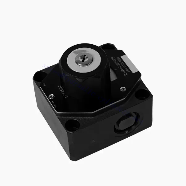
FRM Series Flow Control Hydraulic Valve
FRM Series Flow Control Hydraulic Valve
The FRM series flow control hydraulic valve is a cutting-edge hydraulic component designed to enhance the performance and control of hydraulic systems. With its advanced features and reliable functionality, this valve offers precise flow control and optimal efficiency.
The FRM series flow control hydraulic valve is a reliable and versatile solution for optimizing flow control in hydraulic systems. With its precise flow control capabilities, pressure and temperature stability, and durable construction, this valve offers enhanced performance and efficiency. Following the recommended usage methods and maintenance guidelines, operators can maximize the benefits of the FRM series flow control hydraulic valve, ensuring smooth operation and reliable flow control in their hydraulic applications. Upgrade your hydraulic system with this advanced valve and experience precision, efficiency, and productivity like never before.
FRM Series Flow Control Hydraulic Valve Key Characteristics:
- Flow Control Precision:
- The FRM series valve enables precise control over the flow rate of hydraulic fluids, allowing operators to fine-tune and regulate the speed of actuators.
- With its exceptional accuracy, this valve ensures consistent flow control, resulting in improved system performance and enhanced productivity.
- Çok Yönlü Uygulama:
- The FRM series valve is highly versatile and compatible with various hydraulic systems, including industrial machinery, construction equipment, and mobile applications.
- Its adaptability makes it an ideal choice for a wide range of hydraulic setups, providing reliable and efficient flow control.
- Basınç ve Sıcaklık Kararlılığı:
- This hydraulic valve is designed to maintain consistent flow control even under varying pressure and temperature conditions.
- It ensures stable performance and prevents flow fluctuations, safeguarding the integrity and reliability of the hydraulic system.
- Dayanıklı Yapı:
- The FRM series valve is constructed with high-quality materials, ensuring durability and long-term reliability in demanding operating environments.
- Its robust design allows it to withstand high pressures, vibrations, and temperature extremes, providing a dependable solution for hydraulic applications.
FRM Series Flow Control Hydraulic Valve Parameter:
NG6
| Akış kontrol vanası | |||||||||||
| Maksimum çalışma basıncı - Port A | çubuk | 315 | |||||||||
| B'den A'ya serbest dönüş akışı için basınç farkı ΔP | Karakteristik eğrilere bakın | ||||||||||
| Minimum basınç farkı | çubuk | 6 ila 14 | |||||||||
| P= 315 bara kadar basınç kararlılığı | % | ±2(Qmaks) | |||||||||
| Akış | Qmax | L/dak | 0.2 | 0.6 | 1.5 | 3 | 6 | 10 | 16 | 25 | 32 |
| Qmin ila 100bar | mL/dakika | 15 | 15 | 15 | 15 | 25 | 50 | 70 | 100 | 250 | |
| Qmin ila 315bar | 25 | 25 | 25 | 25 | 25 | 50 | 70 | 100 | 250 | ||
| Sıvı | Mineral yağ, Fosfat esteri | ||||||||||
| Sıvı sıcaklık aralığı | ℃ | – 20 ila + 80 | |||||||||
| Viskozite aralığı | mm2/s | 10 ila 800 | |||||||||
| Kirlilik derecesi | İzin verilen maksimum sıvı kirliliği derecesi: Sınıf 9. NAS 1638 veya 20/18/15, ISO4406 | ||||||||||
| Kurulum pozisyonu | İsteğe bağlı | ||||||||||
| Koşullar sıcaklık aralığı | ℃ | -20 ila +50 | |||||||||
| Ağırlık | 2FRM6A…2FRM6B… | kilogram | yaklaşık 1.3 | ||||||||
| 2FRM6SB… | kilogram | yaklaşık 1,5 | |||||||||
| Doğrultucular | |||||||||||
| Nominal akış | çubuk | 320 | |||||||||
| Maksimum çalışma basıncı | çubuk | 210'a kadar | |||||||||
| Çatlak basıncı | çubuk | 0.7 | |||||||||
| Ağırlık | kilogram | yaklaşık 0,9 | |||||||||
NG5/10/16
| Akış kontrol vanası | ||||||||||||||||
| Maksimum çalışma basıncı - Port A | çubuk | 315 | ||||||||||||||
| B'den A'ya serbest dönüş akışı için basınç farkı ΔP | Karakteristik eğrilere bakın | |||||||||||||||
| Minimum basınç farkı | çubuk | 6 ila 14 | ||||||||||||||
| Sıvı | Mineral yağ, Fosfat esteri | |||||||||||||||
| Sıvı sıcaklık aralığı | ℃ | – 20 ila + 80 | ||||||||||||||
| Viskozite aralığı | mm2/s | 10 ila 800 | ||||||||||||||
| Kirlilik derecesi | İzin verilen maksimum sıvı kirliliği derecesi: Sınıf 9. NAS 1638 veya 20/18/15, ISO4406 | |||||||||||||||
| Boyut | mm | 5 | 10 | 16 | ||||||||||||
| Maksimum akış hızı | L/dak | 0.2 | 0.6 | 1.2 | 3 | 6 | 10 | 15 | 10 | 16 | 25 | 50 | 60 | 100 | 160 | |
| Yağ dönüş akışı B'den A'ya | mL/dakika | 0.5 | 0.5 | 0.6 | 0.9 | 1.8 | 3.6 | 6.7 | 2 | 2.5 | 3.5 | 6 | 2.8 | 4.3 | 7.3 | |
| akış kararlı aralığı (%Qmax)(-20-±80℃) | ±5 | ±3 | ±2 | ±2 | ||||||||||||
| ±2 (P=210 bar) | ±2 (P=350 bar) | |||||||||||||||
| Çalışma basıncı | çubuk | 210 | 350 | |||||||||||||
| Min. basınç düşüşü | çubuk | 3-5 | 6-8 | 3-7 | 5-12 | |||||||||||
| Ağırlık | kilogram | 1.6 | 3.4 | 7.4 | ||||||||||||
| Doğrultucular | ||||||||||||||||
| Sıvı | Mineral yağ, Fosfat esteri | |||||||||||||||
| Sıvı sıcaklık aralığı | -20 ila +80 | |||||||||||||||
| Viskozite aralığı | 10 ila 800 | |||||||||||||||
| Kirlilik derecesi | İzin verilen maksimum sıvı kirliliği derecesi: Sınıf 9. NAS 1638 veya 20/18/15, ISO4406 | |||||||||||||||
| Boyut | 5 | 10 | 16 | |||||||||||||
| Akış | 15 | 50 | 160 | |||||||||||||
| Çalışma basıncı | 210 | 315 | 315 | |||||||||||||
| Çatlak basıncı | 1 | 1.5 | 1.5 | |||||||||||||
| Ağırlık | 0.6 | 3.2 | 9.3 | |||||||||||||
FRM Series Flow Control Hydraulic Valve Advantages:
• Taban alt plaka montajı için ürün kataloğuna bakın
• Basınç dengeleme yer değiştirme sınırlayıcısı, opsiyonel
• İsteğe bağlı tek yönlü valf
• Ölçekli düğme, isteğe bağlı kilitleme
Usage Method Of FRM Series Flow Control Hydraulic Valve:
- Sistem Değerlendirmesi:
- Begin by assessing the hydraulic system’s requirements, including flow rates, pressure ranges, and desired flow control parameters.
- Determine if the FRM series valve suits the specific application based on its flow control capabilities.
- Vana Seçimi:
- Select the appropriate variant of the FRM series valve based on the system parameters, desired flow rate, and compatibility with other system components.
- Maksimum akış kapasitesi, basınç derecesi ve çalışma koşulları gibi faktörleri göz önünde bulundurun.
- Kurulum:
- Follow the manufacturer’s installation instructions carefully, ensuring proper alignment and secure valve connections.
- Pay attention to the flow direction indicators, ensuring the correct positioning of the valve in the hydraulic system.
- Akış Kontrol Ayarı:
- Once installed, adjust the flow control settings of the valve according to the desired flow rate and system requirements.
- Fine-tune the valve to achieve the desired speed and performance of hydraulic actuators, optimizing the overall system operation.
How Hydraulic Valves Work?
Hydraulic valves are crucial in controlling the flow and direction of hydraulic fluid within a hydraulic system. They are essential components that enable the precise operation of various hydraulic machinery and equipment. Here’s a simplified explanation of how hydraulic valves work:
- Basics of Hydraulic Systems:
Hydraulic systems use fluid, typically oil, to transmit power and control the movement of mechanical components. These systems consist of a hydraulic pump that pressurizes the liquid, a series of valves that control the flow and direction of the fluid, and hydraulic actuators (such as cylinders or motors) that convert the fluid energy into mechanical force or motion. - Valve Types:
There are various hydraulic valves, including directional control valves, pressure control valves, flow control valves, and check valves. Each valve type serves a specific purpose in regulating fluid flow, pressure, or direction. - Directional Control Valves:
Directional control valves determine the path through which the hydraulic fluid flows. They have multiple positions (such as open, closed, or partially open) and multiple ports to direct the fluid to different sections of the hydraulic system. - Valve Components:
Hydraulic valves typically consist of a valve body, which contains internal passages and channels, and a movable valve element or spool that slides within the valve body. The spool has different lands or ports that align with the internal passages to control fluid flow. - Spool Movement:
The position of the spool within the valve body determines the flow path and, consequently, the direction of fluid flow. The spool can be actuated by various means, such as mechanical linkages, solenoids, or pilot pressure. - Pressure Control Valves:
Pressure control valves regulate the pressure of the hydraulic fluid within the system. They can maintain a specific pressure level by allowing excess fluid to return to the reservoir or blocking flow until a desired pressure is reached. - Akış Kontrol Vanaları:
Flow control valves manage the rate of fluid flow within the hydraulic system. They can be used to control the speed of hydraulic actuators or to limit the flow rate to specific sections of the system. - Check Valves:
Check valves, or one-way valves, allow fluid flow in one direction and prevent backflow. They ensure that the fluid moves in the desired direction and avoid any undesired pressure drops or loss of hydraulic force. - Vana Hareketi:
Hydraulic valves can be manually operated, mechanically actuated, or controlled electronically. Levers or knobs directly handle manual valves, while mechanical and electronic actuators enable automated control of valve positions based on system requirements. - System Control:
By combining different types of hydraulic valves and controlling their positions or actuation, the hydraulic system’s overall function can be precisely regulated. This enables operators to control the movement, speed, force, and direction of hydraulic actuators, allowing for precise and efficient operation of hydraulic machinery.
Fabrikanın Kapasitesi ve Kapasitesi:
(1) Meclis
Birinci sınıf bağımsız bir araştırma ve geliştirme montaj platformumuz bulunmaktadır. Hidrolik silindir üretim atölyemizde, yıllık 1 milyon adet üretim kapasitesine sahip dört adet yarı otomatik kaldırma silindiri montaj hattı ve bir adet otomatik devirme silindiri montaj hattı bulunmaktadır. Özel silindir atölyemiz, yıllık 200.000 adet üretim kapasitesine sahip çeşitli özelliklerde yarı otomatik temizleme montaj sistemiyle donatılmıştır. Ayrıca, ünlü CNC işleme ekipmanları, bir işleme merkezi, yüksek hassasiyetli silindir işleme özel ekipmanları, bir robot kaynak makinesi, bir otomatik temizleme makinesi, otomatik silindir montaj makinesi ve otomatik boyama üretim hattı ile donatılmıştır. 300'den fazla setten oluşan kritik ekipmanlar mevcuttur. Ekipman kaynaklarının optimum dağılımı ve verimli kullanımı, ürünlerin hassasiyet gereksinimlerini karşılar ve ürünlerin yüksek kalite ihtiyaçlarını karşılar.


(2) İşleme
İşleme atölyesi, maksimum 400 mm iç çapa ve maksimum 6 metre uzunluğa sahip silindir borularının işlenmesini gerçekleştirebilen özel eğimli ray torna merkezi, işleme merkezi, yüksek hızlı honlama makinesi, kaynak robotu ve diğer ilgili ekipmanlarla donatılmıştır.

(3) Kaynak

(4) Boyama ve kaplama
Küçük ve orta ölçekli silindirli otomatik su bazlı boya kaplama hatlarında, otomatik robot yükleme-boşaltma ve otomatik püskürtmeyi gerçekleştirmek için, vardiya başına 4000 adet tasarım kapasitesi;
Ayrıca, vardiya başına 60 kasa kapasiteli, güç zinciriyle çalışan büyük silindirler için yarı otomatik boya üretim hattımız da bulunmaktadır.


(5) Test etme
Silindirin performansının gereklilikleri karşıladığından emin olmak için birinci sınıf muayene tesislerimiz ve test yataklarımız bulunmaktadır.

En iyi hidrolik silindir üreticilerinden biriyiz. Kapsamlı hidrolik silindirler sunabiliyoruz. Ayrıca, ilgili hidrolik silindirleri de sağlıyoruz. tarımsal dişli kutularıÜrünlerimizi dünya çapındaki müşterilerimize ihraç ettik ve üstün ürün kalitemiz ve satış sonrası hizmetlerimiz sayesinde iyi bir itibar kazandık. Yurt içi ve yurt dışındaki müşterilerimizi iş görüşmeleri yapmak, bilgi alışverişinde bulunmak ve bizimle işbirliği yapın!


