
Гідравлічний розподільник серії WMR з механічним ручним керуванням
Гідравлічний розподільник серії WMR з механічним ручним керуванням
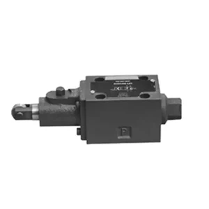
The WMR series directional hydraulic valve with mechanical, manual operation is a cutting-edge solution designed to deliver precise control in hydraulic systems. This valve offers enhanced efficiency and flexibility with its advanced features and robust construction.
The WMR series directional hydraulic valve with mechanical, manual operation is a reliable and versatile solution for hydraulic systems. Its automatic and manual operation and precise directional control offer enhanced flexibility and control for various applications. Following the recommended usage methods and adhering to regular maintenance practices, the WMR series valve will continue providing efficient and reliable operation. Upgrade your hydraulic system with the WMR series directional hydraulic valve and experience the benefits of enhanced control and versatility.
WMR Series Directional Hydraulic Valve With Mechanical, Manual Operation Key Characteristics:
- Mechanical, Manual Operation:
- The WMR series valve features a mechanical, manual operation, allowing operators to control the valve position manually.
- This provides flexibility and control in applications where manual operation is desired or required.
- Напрямний контроль:
- This hydraulic valve enables precise directional fluid flow control within the hydraulic system.
- It allows operators to select the desired flow path, ensuring efficient and reliable operation.
- Міцна конструкція:
- The WMR series valve is constructed with high-quality materials, ensuring durability and longevity.
- Its robust design can withstand demanding operating conditions, providing reliable performance.
- Широкий спектр застосування:
- The WMR series valve suits various industries and applications, including manufacturing, construction, agriculture, etc.
- It can be utilized in hydraulic systems that require accurate and efficient fluid control.
WMR Series Directional Hydraulic Valve With Mechanical, Manual Operation Parameter:
НГ6
| Положення встановлення | Необов'язково | ||
| Діапазон температур рідини | ℃ | -30 до +80 (ущільнення NBR) | |
| -20 до +80 (ущільнення FKM) | |||
| Порт Макс. робочий тиск | Порт ABP | бар | 315 |
| Порт Т | бар | 60 | |
| Макс. витрата | л/хв | 60 | |
| Поперечний переріз потоку (перемикання нейтрального положення) | Тип Q | мм2 | Для символу Q, 6% номінального поперечного перерізу |
| Тип W | мм2 | Для символу W, 3% номінального поперечного перерізу | |
| Рідина | Мінеральна олія; фосфатний ефір | ||
| Діапазон в'язкості | мм2/с | від 2,8 до 500 | |
| Ступінь забруднення | Максимально допустимий ступінь забруднення рідини: Клас 9. NAS 1638 або 20/18/15, ISO4406 | ||
| Вага | кг | 1.4 | |
НГ10
| Положення встановлення | Необов'язково | ||
| Діапазон температур рідини | ℃ | -30 до +80 (ущільнення NBR) | |
| -20 до +80 (ущільнення FKM) | |||
| Порт Макс. робочий тиск | Порт ABP | бар | 315 |
| Порт Т | бар | 60 | |
| Макс. витрата | л/хв | 120 | |
| Поперечний переріз потоку (перемикання нейтрального положення) | V-подібний тип | мм2 | 11(А/Б → Т); 10.3(П → А/Б) |
| Тип W | мм2 | 2.5(А/Б → Т) | |
| Тип Q | мм2 | 5.5(А/Б → Т) | |
| Рідина | Мінеральна олія; фосфатний ефір | ||
| Діапазон в'язкості | мм2/с | від 2,8 до 500 | |
| Ступінь забруднення | Максимально допустимий ступінь забруднення рідини: Клас 9. NAS 1638 або 20/18/15, ISO4406 | ||
| Вага | кг | 4 | |
WMR Series Directional Hydraulic Valve With Mechanical, Manual Operation Advantages:
• Прямий спрямований золотниковий клапан прямої дії спрямований золотниковий клапан прямої дії
• Колесо прокручування може обертатися на 90°
• Дев'ятнадцять стандартних функцій золотникового клапана
Usage Method Of WMR Series Directional Hydraulic Valve With Mechanical, Manual Operation:
- Системна інтеграція:
- Identify the appropriate location for the WMR series valve within the hydraulic system, considering the desired flow direction and control requirements.
- Переконайтеся, що система відповідає вимогам щодо тиску та витрати.
- Надійно закріпіть клапан за допомогою відповідних кронштейнів або монтажних аксесуарів.
- З'єднання рідин:
- Оберіть сумісні гідравлічні фітинги та шланги для надійних з'єднань без протікань.
- Дотримуйтесь інструкцій виробника щодо належних значень крутного моменту під час процесу встановлення.
- Use appropriate thread sealants or tape to ensure a reliable seal.
- Manual Operation:
- Familiarize yourself with the manual operation mechanism of the valve, including the lever or knob used to control the valve position.
- Ensure the operator understands the correct procedure for manually adjusting the valve position.
- Калібрування системи:
- Calibrate the valve position and movement according to the desired flow direction and control requirements.
- Adjust the valve manually to achieve the desired flow path and ensure proper functionality.
How To Adjust Hydraulic Valve Lifters?
Adjusting hydraulic valve lifters is a crucial maintenance task to ensure proper engine performance and prevent issues like valve train noise and reduced power. Here’s a step-by-step guide on how to adjust hydraulic valve lifters:
- Prepare the Engine:
- Before starting the adjustment process, make sure the engine is turned off and cool to the touch.
- Remove any components necessary to access the valve covers, such as the air cleaner assembly or spark plug wires.
- Identify the Correct Valve Adjustment Sequence:
- Consult the engine manufacturer’s specifications or service manual to determine the correct valve adjustment sequence for your specific engine.
- Some engines have a firing order that dictates the sequence, while others have specific instructions based on cylinder numbering.
- Locate the Top Dead Center (TDC) Position:
- Rotate the engine’s crankshaft in the normal direction of rotation until the number one piston reaches the top dead center (TDC) position on its compression stroke.
- Use a timing mark on the harmonic balancer or flywheel and a timing pointer to determine the TDC position accurately.
- Adjusting Valve Lifters:
- Start with the first cylinder in the valve adjustment sequence.
- Remove the valve cover to access the rocker arms and valve lifters.
- Loosen the lock nut on the rocker’s arm using an appropriate wrench or socket.
- Turn the adjusting screw or stud on the rocker’s arm clockwise to decrease the valve clearance or counterclockwise to increase it.
- Check the engine manufacturer’s specifications for the recommended valve clearance. Use a feeler gauge to measure the clearance between the rocker arm and the valve stem.
- Adjust the valve lifter until the proper clearance is achieved. You should feel slight resistance but still be able to move the feeler gauge back and forth.
- Hold the adjusting screw or stud in place and tighten the lock nut securely.
- Повторіть процес:
- Move to the next cylinder in the valve adjustment sequence and repeat steps 4 and 5 until all the valve lifters have been adjusted.
- Reinstall Valve Covers:
- Once you’ve completed the valve adjustment on all cylinders, reinstall the valve covers and ensure they are properly sealed to prevent oil leaks.
- Double-Check:
- After adjusting the valve lifters, it’s advisable to go through the entire valve adjustment sequence once more to confirm that all clearances are within the specified range.
Можливості та потужність заводу:
(1) Асамблея
Ми маємо першокласну незалежну платформу для досліджень та розробок. Цех виробництва гідравлічних циліндрів має чотири напівавтоматичні лінії складання підйомних циліндрів та одну автоматичну лінію складання нахилених циліндрів з проектною річною виробничою потужністю 1 мільйон одиниць. Цех спеціальних циліндрів оснащений різними специфікаціями напівавтоматичної системи очищення та складання з проектною річною виробничою потужністю 200 000 одиниць, а також оснащений відомим обладнанням з ЧПУ, обробним центром, високоточним спеціальним обладнанням для обробки циліндрів, роботизованим зварювальним апаратом, автоматичною машиною очищення, автоматичною машиною складання циліндрів та автоматичною виробничою лінією фарбування. Існуюче критично важливе обладнання налічує понад 300 комплектів. Оптимальний розподіл та ефективне використання ресурсів обладнання забезпечує вимоги до точності продукції та задоволення потреб у високій якості продукції.


(2) Механічна обробка
Механічний цех оснащений спеціалізованим токарним центром для похилих рейок, обробним центром, високошвидкісним хонінгувальним верстатом, зварювальним роботом та іншим супутнім обладнанням, яке може обробляти циліндричні труби з максимальним внутрішнім діаметром 400 мм та максимальною довжиною 6 метрів.

(3) Зварювання

(4) Фарбування та покриття
З малими та середніми циліндричними автоматичними лініями нанесення фарби на водній основі, для досягнення автоматичного завантаження та розвантаження роботів та автоматичного розпилення, проектна потужність 4000 штук за зміну;
У нас також є напівавтоматична лінія з виробництва фарби для великих балонів, що живиться від ланцюга, з проектною потужністю 60 корпусів за зміну.


(5) Тестування
Ми маємо першокласне обладнання для інспекції та випробувальні стенди, щоб гарантувати, що характеристики циліндра відповідають вимогам.

Ми є одним з найкращих виробників гідравлічних циліндрів. Ми можемо запропонувати комплексні гідравлічні циліндри. Ми також надаємо відповідні сільськогосподарські коробки передачМи експортуємо нашу продукцію клієнтам по всьому світу та заслужили гарну репутацію завдяки високій якості нашої продукції та післяпродажному обслуговуванню. Ми раді вітати клієнтів як удома, так і за кордоном, щоб зв'язатися з нами для ведення бізнесу, обміну інформацією та... співпрацюйте з нами!


